5 ventilation and cooling, Ventilation and cooling – GE Industrial Solutions TLE Series 225-500 Installation Guide User Manual
Page 22
Critical Power
Modifications reserved
Page 22/54
GE_UPS_ISG_TLE_SUL_M22_M50_1US_V010.docx
Installation Guide TLE Series 225 - 500 UL S1
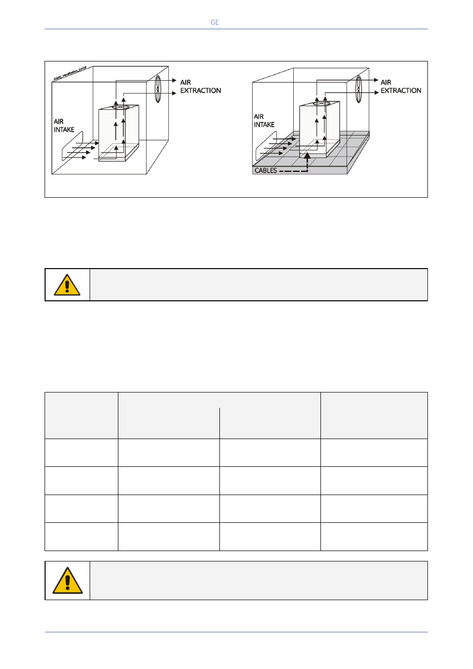
4.5 VENTILATION AND COOLING
Fig. 4.5-1 Installation on plain floor
Fig. 4.5-2 Installation on raised floor
The heat produced by the UPS is transferred to the environment by its ventilation.
Air inlets for UPS ventilation are located on the front of the UPS, while air outlets are on top of the
cabinet.
A suitable ventilation or cooling system must be installed to extract the heat from the UPS room.
NOTE !
Do not put anything on the top of the cabinet.
Air filtering systems could be required when the UPS operates in a dirty environment.
In order to prevent overheating of the UPS, the available air intake flow rate must exceed the total air
exhaust flow rate requirement of the UPS system.
Contact your Dealer or the nearest Service Center for appropriate solutions.
The below table indicates the heat dissipation at full Load at PF = 1 and charged Battery, up to 3280 ft
(1000 m) altitude, for cooling air 77°F (25°C) to 86°F (30°C).
UPS model
Losses
Cooling air flow
VFI
eBoost™ (option)
VFI
PF = 1
PF = 1
PF = 1
TLE Series 225
27845 BTU / hr
8.2 kW
10901 BTU / hr
3.2 kW
1698 CFM
2885 m
3
/h
TLE Series 250
31856 BTU / hr
9.3 kW
10361 BTU / hr
3.0 kW
1784 CFM
3031 m
3
/h
TLE Series 400
48038 BTU / hr
14.1 kW
17977 BTU / hr
5.3 kW
2710 CFM
4605 m
3
/h
TLE Series 500
63712 BTU / hr
18.7 kW
20722 BTU / hr
6.1 kW
3294 CFM
5597 m
3
/h
NOTE !
Even when eBoost™ Operating Mode option is available, the ventilation and cooling
system shall be rated as for operation in VFI mode.