Use of tle series 225 - 500 as frequency converter – GE Industrial Solutions TLE Series 225-500 Installation Guide User Manual
Page 41
Critical Power
Modifications reserved
Page 41/54
GE_UPS_ISG_TLE_SUL_M22_M50_1US_V010.docx
Installation Guide TLE Series 225 - 500 UL S1
4.8.6 Use of TLE Series 225 - 500 as frequency converter
NOTE !
The UPS needs the connection of the Neutral at the input Bus Bars.
When the TLE Series 225 - 500 is utilized for different output frequency compared to the input
frequency, the Automatic Bypass and Manual Bypass functions are disabled, therefore the Load cannot
be transferred to Utility in case of overload, short circuit, or inverter failure.
In situations where the UPS needs to be powered down for maintenance purposes, the critical Load
must also be powered down during this time.
The UPS cannot be transferred to Manual Bypass, as serious damage to the Load could be the result.
When the set-up parameters of the UPS are set for frequency converter, the eBoost™ Operation Mode
is automatically disabled.
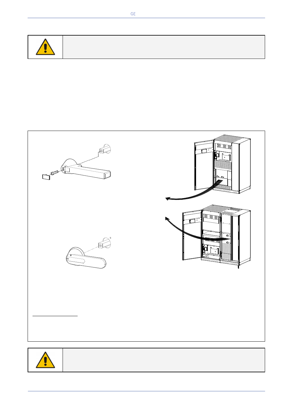
Fig. 4.8.6-1 TLE Series 225 - 500 - Switch Q2 – Manual Bypass
When the UPS is used as a frequency converter, the circuit breaker Q2 - Manual Bypass operating
handle should be removed to avoid any accidental closure. See Fig. 4.8.4-1.
In order to avoid improper operation, only the Rectifier input should be powered (L1-1, L2-1 and L3-1
/ Fig. 4.8.2-1 & 4.8.4.1), therefore the interconnection links BR1, BR2 and BR3, on the input bus bars,
MUST BE REMOVED. See Fig. 4.8.2-2 and 4.8.4-2.
Special care must be taken in choosing the fuse ratings installed in the output distribution (max.
20% of the UPS rated current).
Avoid high inrush current due to transformer magnetization or motor starting.
NOTE !
At site only a QUALIFIED SERVICE ENGINEER may change a unit, initially delivered
as a frequency converter, into a normally operating “standard” UPS.
Q2
Q1
1
2
I ON
0
O
FF
Q2
I ON
0
O
FF
- +
I ON
0 OF
F
TLES_UL_4
00-500_S1_
UPS-Switc
h Q2_01
Q1
I ON
0
O
FF
Q2
I ON
0
O
FF
1
2
-
+
I ON
O OFF