SCANTECH ID (Champtek company) Discovery SG-20 User Manual
Page 41
Scantech-ID Discovery SG-20
33
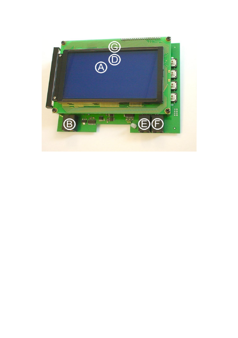
The main board contains the following parts, as marked in the illustrations:
A.
Power inlet; connected to the powersupply.
B.
Port for communication with the back office system.
C.
Jumpers for interface configuration and speaker-connector; P9 is the
speaker connector, J6, J1, J3 and J2 are used for configuration settings
(on systems up to version A360104).
D.
Centronics printer port.
E.
Full RS-232 port (P4), e.g. Chip Card reader.
F.
Full RS-232 port (P3), e.g. Internal Scanner.
G.
RS-232 port data reception only (P2), e.g. additional handscanner.
In a standard configuration, port 3 is used for the build-in Scantech Scanner;
port 2 can be used to connect a hand-held scanner. Port P4 can be used to
connect an additional serial device.
Port P5 can be used to connect a printer.
See Appendix A for the cable work and connector requirements.