Rs-232 connections, Rs-232 signal convention (dte / dce), Wiring an rs-232 device to the radio modem – B&B Electronics ZXT9-RM-KIT - Manual User Manual
Page 23
Document Number: pnZXTxRM-0712m
Page
23
4.1.3 RS-232 Connections
4.1.3.1
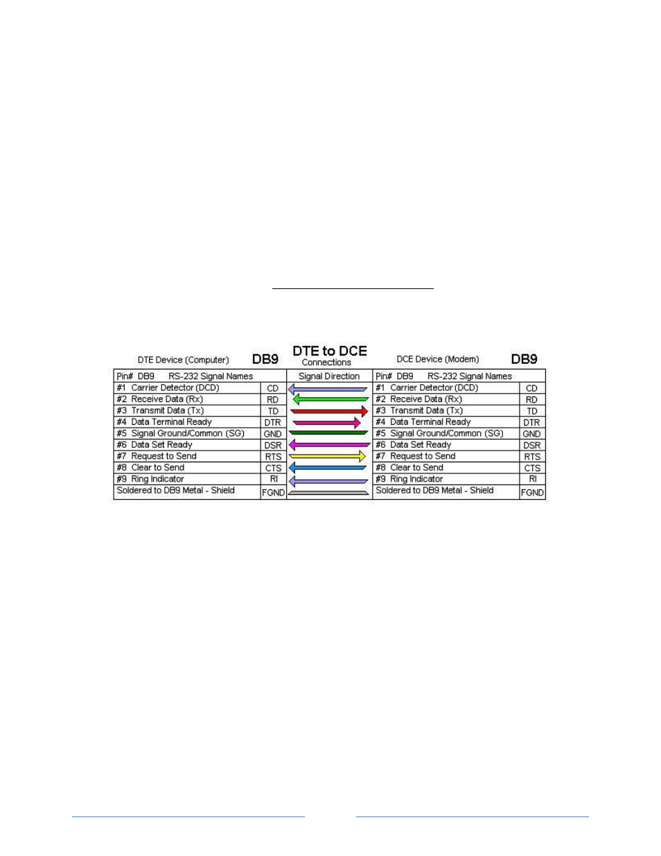
RS-232 Signal Convention (DTE / DCE)
There are two types of RS-232 ports, DTE (Data Terminal Equipment)
and DCE (Data Communications Equipment). The signal names and pin
numbers are the same, but signal flow is opposite. The pin labeled TD
can be input, and RD the output.
The two ports types are complementary, the Output signals on a DTE
port are Inputs to a DCE port, and Output signals on a DCE port are
Inputs to a DTE port. The signal names match each other and connect
pin for pin. Signal flow is in the direction of the arrows.
The Radio Modem is a DCE device.
Figure 4-2 shows RS-232 DTE to RS-232 DCE connections with
associated DB9 Pin Numbers and the signal direction.
Figure 4-2
Terminal Block
4.1.3.2
Wiring an RS-232 Device to the Radio Modem
The Radio Modem supports TD, RD, RTS, and CTS. Please note that if
Sleep Mode is enabled, the DTR signal is used to “wake up” the device.
Figure 4-3 is a wiring diagram for connecting a DTE device such as a
computer or PLC.