Electrical installation, Iring, Terminal block – B&B Electronics ZXT9-RM-KIT - Manual User Manual
Page 22: Power supply connections
Document Number: pnZXTxRM-0712m
Page
22
Section Four
– Electrical Installation
4.0 Electrical Installation
Please see the Quick Start Guide for UL Class 1 Division 2 installation instructions.
4.1 Wiring
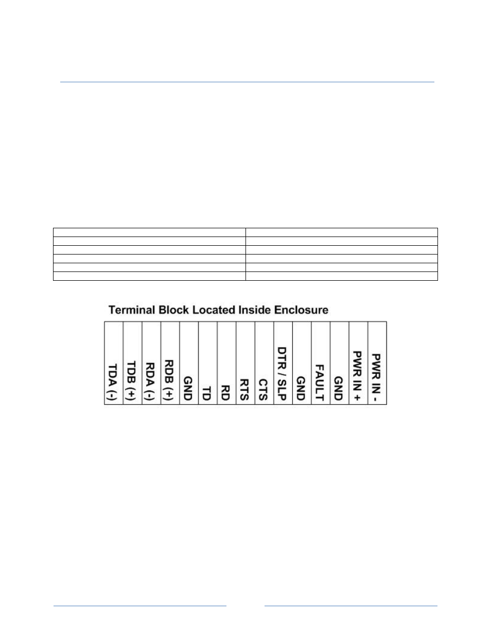
4.1.1 Terminal Block
Both power and data signals are connected to the terminal block. Figure 4-1 shows the
layout.
Operating Voltage
10 to 20 VDC
Maximum Surrounding Ambient Air Temp
74°C
Wiring Terminals
Use Copper Wire Only, One Conductor Per Terminal
Wire Range
30 to 12 AWG
Tightening Torque
0.5 to 0.6 Nm
Temperature Rating of Field Installed Conductors
105°C minimum, sized for 60°C ampacity.
Figure 4-1
Terminal Block
4.1.2 Power Supply Connections
The radio modem requires power from an external source. The radio modem requires 10
to 30 VDC. Power use depends on the model:
ZXT9RM
– 1.7 Watts typical, 5.8 Watts maximum.
ZXT24RM
– 1.2 Watts typical, 3.5 Watts maximum.
Connect the positive and negative power leads to the Power In(+) and Power In (-)
terminals on the terminal block.
.