2 run state, Sequence a sequence b, Symbol parameter comments min typ max units t – Rainbow Electronics AT73C246 User Manual
Page 31: Vdd4 shutdown time vdd4 is off in run st ate
31
11050A–PMAAC–07-Apr-10
AT73C246
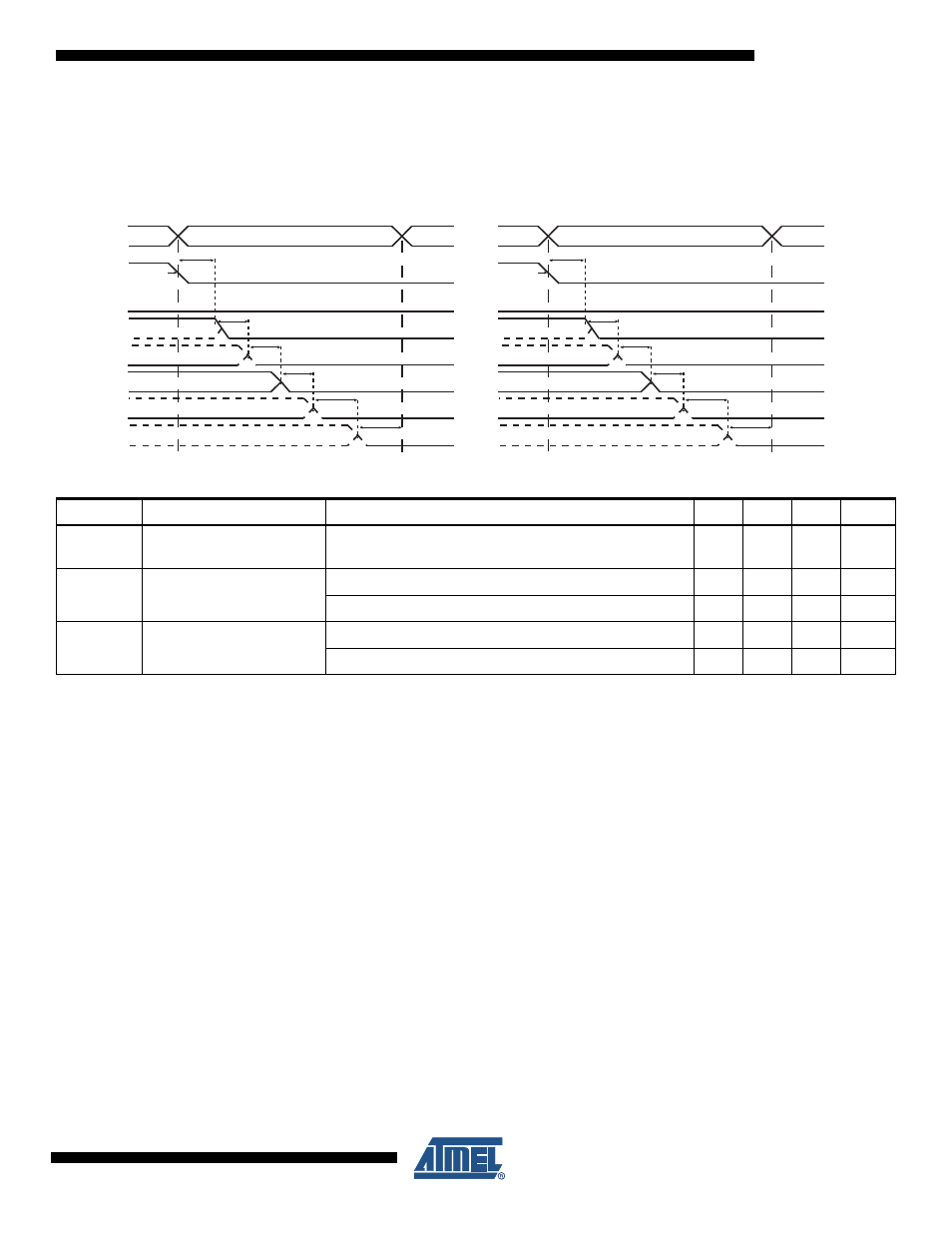
When the POWERDOWN state is reached from the STANDBY state, the CPU power supplies
are switched off sequentially as described in
.
Figure 11-4. AT73C246 - STANDBY to POWERDOWN state Supplies Shutdown timing diagram.
Notes: 1. VDDx activity during STANDBY state is set by register PMU_STANDBY_SUPPLIES.
2. VDD4 activity during RUN state is set by Bit7 of register VDD4_CTRL.
11.4.2
RUN STATE
When AT73C246 is in RUN state:
• VDD
{0,1,2,3,5}
power supplies are ON.
• RSTB pin is released.
• PMU functions are under software control (LDO4, AUDIO CODEC, ADC Controller)
• Led pin is driven according to register PMU_LED (0x0B).
Table 11-3.
STANDBY to POWERDOWN state timing table
Symbol
Parameter
Comments
Min
Typ
Max
Units
T
STBY_OUT
STANDBY OUT Event
detection time
95
100
105
µs
T
OFF_VDDx
VDDx SHUTDOWN Time
VDDx is OFF during STANDBY state
58
62
66
µs
VDDx is ON during STANDBY state
4.8
5.2
5.4
ms
T
OFF_VDD4
VDD4 SHUTDOWN Time
VDD4 is OFF in RUN state
58
62
66
µs
VDD4 is ON in RUN state
4.8
5.2
5.4
ms
STANDBY
STATE
SUPPLIES SHUTDOWN
STANDBY_OUT
EVENT
POWERDOWN
STATE
T
STBY_OUT
T
OFF_VDD2
V
DD2
(1V)
V
DD0
(1.85V)
V
DD3
(3.3V)
1V
1.2V
RSTB
V
DD1
(1.2V)
T
OFF_VDD1
1.85V
T
OFF_VDD0
3.3V
T
OFF_VDD3
V
DD4
(CODEC)
T
OFF_VDD4
STANDBY
STATE
SUPPLIES SHUTDOWN
STANDBY_OUT
EVENT
POWERDOWN
STATE
T
STBY_OUT
T
OFF_VDD3
V
DD3
(3.3V)
V
DD0
(1.85V)
V
DD2
(1V)
3.3V
1.2V
RSTB
V
DD1
(1.2V)
T
OFF_VDD1
1.85V
T
OFF_VDD0
1V
T
OFF_VDD2
V
DD4
(CODEC)
T
OFF_VDD4
SEQUENCE A
SEQUENCE B