Pmu functional description, 1 power manager state diagram, Figure 11-1 “at73c246 power man – Rainbow Electronics AT73C246 User Manual
Page 25
25
11050A–PMAAC–07-Apr-10
AT73C246
11. PMU Functional Description
11.1 Power Manager State Diagram
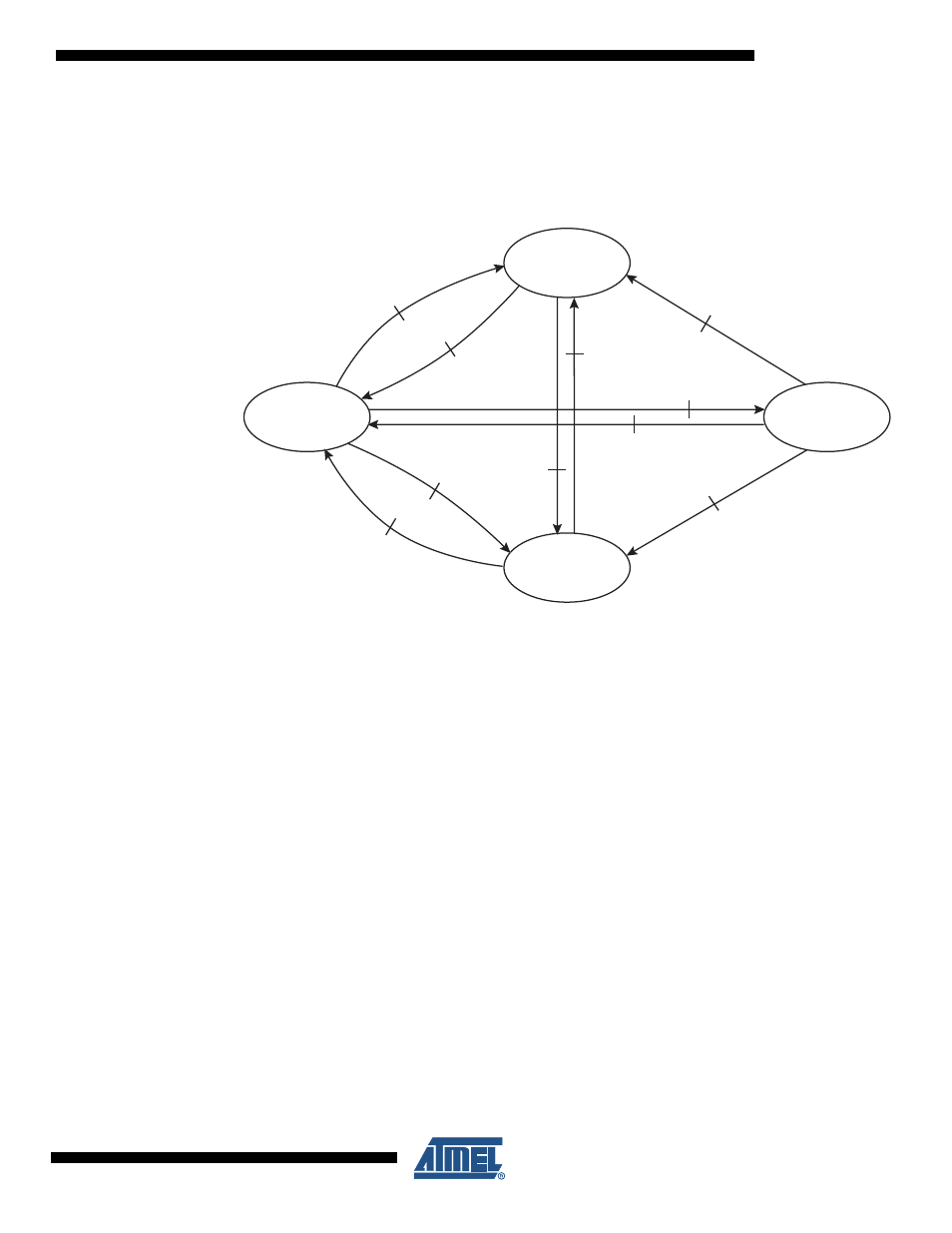
Figure 11-1. AT73C246 Power Manager Functional State Diagram
AT73C246 is placed in POWERDOWN state at VINSYS rising following the PMU startup state
diagram described in
. From this POWERDOWN state, normal CPU sup-
plies startup is achieved through validation of one of the POWER-ON events. From this state,
the PMU may be placed in STANDBY state (e.g.: during CPU sleep periods) upon software
request (STANDBY event). PMU wake-up is achieved if one of the WAKEUP events is detected.
The PMU returns to the POWERDOWN state as soon as a POWER-OFF event is detected. A
special HRST (Hard-Reset) state is provided to ensure complete stop and restart of the CPU
supplies in case of a software crash. Moreover, die temperature and VDD
{0,1,2,3}
supplies are
supervised and may generate a POWER-FAIL event in case of out-of-specification detection.
POWERDOWN
(all supplies OFF)
RSTB = 0
HRST
(all supplies OFF)
RSTB = 0
TWI Reset
STANDBY
(selected supplies ON)
RSTB = 0
RUN
(all supplies ON)
RSTB = 1
POWER-OFF or POWER-FAIL
EVENT
POWER-ON EVENT &
Vin > 3.1V
HRST_POWERDOWN
EVENT
HRST_RUN
EVENT
HRST
EVENT
WAKEUP
EVENT
STANDBY
EVENT
HRST
EVENT
HRST
EVENT
STANDBY-OUT or POWER-FAIL
EVENT