2 pmu startup and shutdown state diagram, Figure 11-2 “at73c246 start-up and shutdown, Rises above 2v: • an internal v – Rainbow Electronics AT73C246 User Manual
Page 26
26
11050A–PMAAC–07-Apr-10
AT73C246
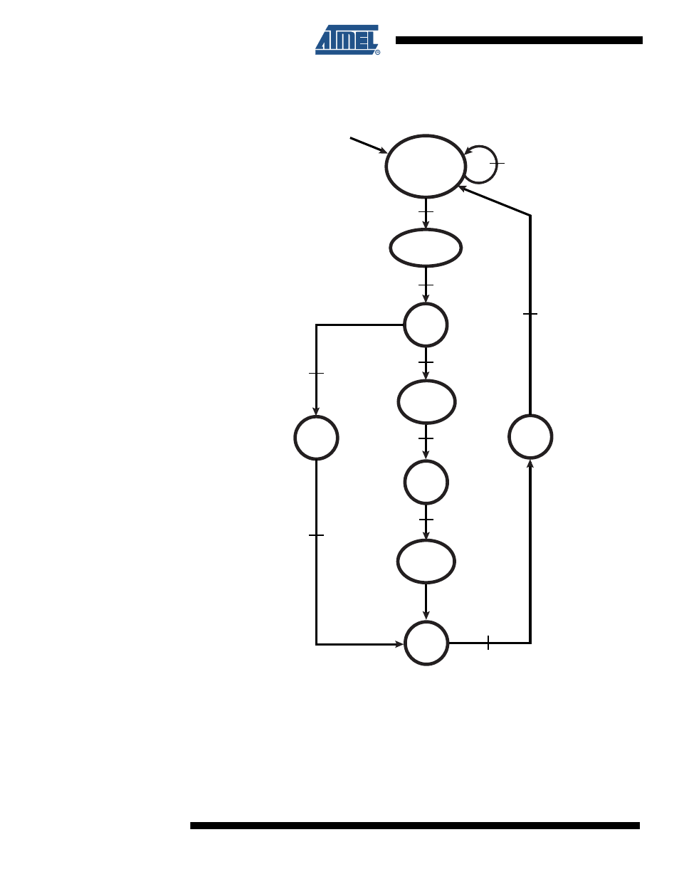
11.2 PMU Startup and Shutdown State Diagram
Figure 11-2. AT73C246 Start-up and Shutdown State Diagram
The start-up of the AT73C246 follows the flow diagram of
and aims at placing the
power manager in the POWERDOWN state.
When V
INSYS
rises above 2V:
• An internal V
INSYS
monitor starts and holds the internal PMU_RSTN and AUDIO_RSTN
signals to 0, thus forcing a complete reset of AT73C246. The PMU digital core supply voltage
Start : V
INSYS
Monitor &
V
DDC
= 1.8V.
PMU_RSTN = 0
AUDIO_RSTN = 0
V
INSYS
< 2.7V
or
V
DDC
_KO
Vin > 2V
V
INSYS
> 2.7V &
V
DDC
_OK
PMU_RSTN = 1
AUDIO_RSTN = 1
1
READ
CONFIG
V
BACKUP
< 1.8V
RTC_RSTN = 0
1
START
LDO5
(BACKUP)
V
BACKUP
> 1.8V
RTC_RSTN = 1
POWER
DOWN
V
BACKUP
> 1.8V
START
LDO5
(BACKUP)
V
BACKUP
> 1.8V
V
INSYS
< 2.7V
OFF
LDO5
(BACKUP)
1
- MAX5151 (16 pages)
- MAXQ3108 (64 pages)
- MAX5661 (39 pages)
- MAX6691 (7 pages)
- MAX5362 (12 pages)
- ADC10158 (26 pages)
- MAX8922L (14 pages)
- MAX8596Z (8 pages)
- MAX7491 (18 pages)
- MAX15040 (15 pages)
- MAX5177 (16 pages)
- ADC08138 (22 pages)
- MAX5961 (42 pages)
- T89C51RD2 (86 pages)
- MAX16055 (9 pages)
- MAX6659 (17 pages)
- ADC0820 (20 pages)
- MAX6678 (19 pages)
- MAX8884Z (15 pages)
- MAX16915 (9 pages)
- MAX8620 (18 pages)
- MAX5144 (12 pages)
- MAX6670 (8 pages)
- MAX8760 (39 pages)
- W78C32C (14 pages)
- MX7533 (8 pages)
- MAX8727 (13 pages)
- MAX9053 (15 pages)
- W78C54 (16 pages)
- MAX8614B (15 pages)
- W90N740 (219 pages)
- MAX6626 (13 pages)
- ADC10738 (30 pages)
- MAX17000 (31 pages)
- MAX5051 (21 pages)
- MAXQ1004 (18 pages)
- MAX6871 (51 pages)
- MX7847 (12 pages)
- MAX6608 (6 pages)
- MAX17083 (15 pages)
- MAX6641 (17 pages)
- MAX5251 (16 pages)
- MAX6338 (8 pages)
- MAX6690 (16 pages)
- MAX8668 (18 pages)