Ttenuation, Ration – Rainbow Electronics AT73C246 User Manual
Page 24
24
11050A–PMAAC–07-Apr-10
AT73C246
Notes: 1. Full Scale: A linear extrapolation to 0dBFS of the measured level at -10dBFS.
2. Signal-to-Noise Ratio: The ratio of the RMS value of a 997Hz full scale sine wave to the RMS value of output noise with no
signal applied. Device is not muted.
3. Dynamic Range: According to AES17-1991 (Audio Engineering Society) and EIAJ CP-307 (Electronic Industries Associa-
tion of Japan), an extrapolation to 0dBFS input signal of the THD+N ratio measurement at -60dBFS. As an example, if
THD+N @ -60dBFS = -36dB, then DR = 96dB.
4. Total Harmonic Distortion + Noise Ratio: The ratio of the RMS sum of the noise and the distortion components to the RMS
value of the signal.
5. XTALK: Attenuation measurement from one channel to the other one. Measurement is performed by stimulated one channel
with a 997Hz / -10dBFS sinewave and leaving the other channel unstimulated.
6. Mute Attenuation: Attenuation measurement of a -10dBFS / 997Hz input signal when concerned gain is set to mute.
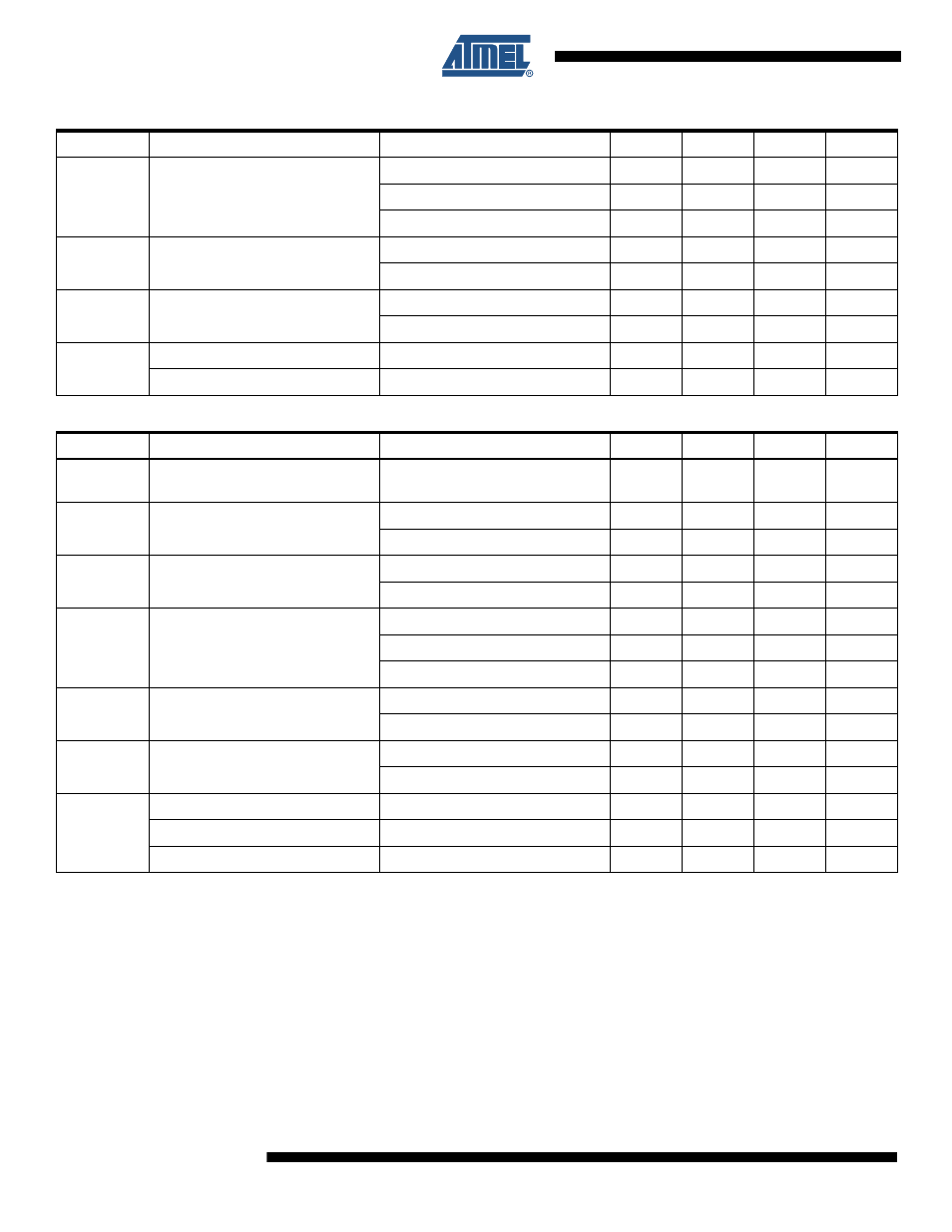
THD
Total Harmonic Distortion
0dBFs input - 10k
Ω load
-
-88
-80
dB
20mW output - 32
Ω load
-
-65
-60
dB
20mW output - 16
Ω load
-
-60
-55
dB
P
O
Output Power
32
Ω load - THD < -40dB or 1%
30
mW
16
Ω load - THD < -40dB or 1%
50
mW
XTALK
Left / Right Channel Separation
10k
Ω AC coupled load
90
dB
16
Ω DC coupled load
60
dB
G
BYP
Bypass Gain
-1
0
+1
dB
Mute Attenuation
80
-
-
dB
Table 10-6.
Analog Sidetone Path: Microphone Input to Headphone Output
Symbol
Parameter
Comments
Min
Typ
Max
Units
V
FS
Full Scale Output Voltage
AVDD /
3.3
V
RMS
SNR
Signal-to-Noise Ratio
AVDD = 3.3V
92
97
-
dB
AVDD = 2.7V
89
94
-
dB
DR
Dynamic Range
AVDD = 3.3V
92
97
-
dB
AVDD = 2.7V
89
94
-
dB
THD
Total Harmonic Distortion
0dBFs input - 10k
Ω load
-
-88
-80
dB
20mW output - 32
Ω load
-
-65
-60
dB
20mW output - 16
Ω load
-
-60
-55
dB
P
O
Output Power
32
Ω load - THD < -40dB or 1%
30
mW
16
Ω load - THD < -40dB or 1%
50
mW
XTALK
Left / Right Channel Separation
10k
Ω AC coupled load
90
dB
16
Ω DC coupled load
60
dB
G
SIDETONE
Programmable Gain Range
-30
-
0
dB
Gain Steps
2.5
3
3.5
dB
Mute Attenuation
80
-
-
dB
Table 10-5.
Analog Bypass Path: Line / Auxiliary Input to Headphone Output
Symbol
Parameter
Comments
Min
Typ
Max
Units