Pmu electrical characteristics, 1 current consumption versus modes, 2 supply monitor thresholds – Rainbow Electronics AT73C246 User Manual
Page 12
12
11050A–PMAAC–07-Apr-10
AT73C246
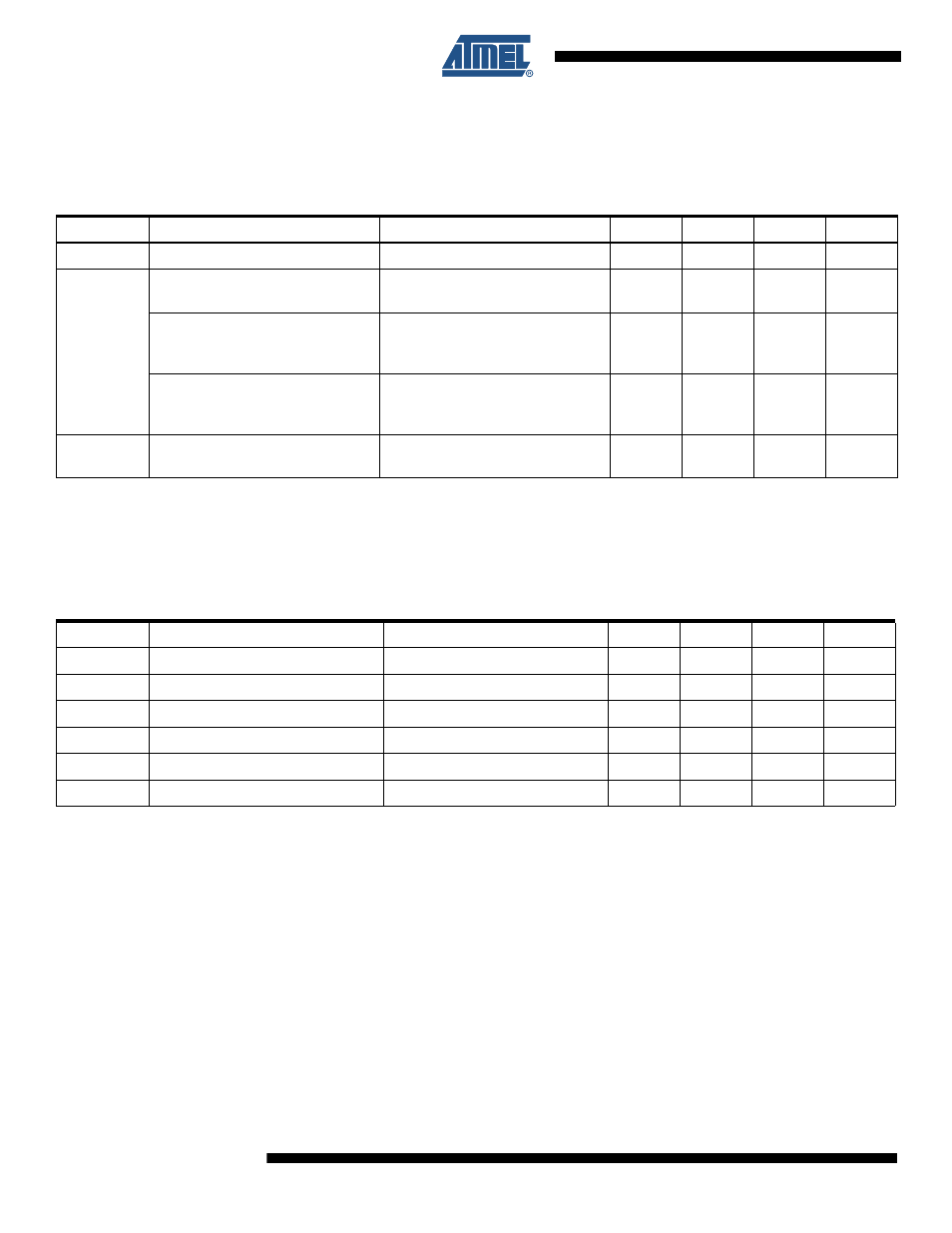
9. PMU Electrical Characteristics
9.1
Current Consumption Versus Modes
9.2
Supply Monitor Thresholds
The following table applies to functional state diagrams of
Figure 11-1 “AT73C246 Power Man-
ager Functional State Diagram” on page 25
Figure 11-2 “AT73C246 Start-up and Shutdown
Table 9-1.
Current Consumption Versus Modes
Symbol
Parameter
Comments
Min
Typ
Max
Units
V
IN
Operating Supply Voltage
V
INSYS,
V
IN{0,1,3,4}
present.
2.9
3.6
5.5
V
I
DD_VIN
POWERDOWN Mode.
All LDOs and DCDC converters
OFF. Audio OFF. RTC running.
-
20
40
µA
RUN Mode.
All LDOs and DCDC converters
running in PWM. Audio OFF. RTC
running.
-
7
15
mA
STANDBY Mode.
Default setup: DCDC0 ON in low-
power mode. LDO3 ON. All other
functions OFF.
-
310
500
µA
I
DD_RTC
All Modes.
RTC running. Total current
entering pin V
BACKUP
1
5
µA
Table 9-2.
Supply Monitor Thresholds
Symbol
Parameter
Comments
Min
Typ
Max
Units
V
IN
> 3.1V
PMU Input 3.1V Rising Threshold
3.070
3.1
3.130
V
V
IN
< 2.9V
PMU Input 2.9V Falling Threshold
2.870
2.9
2.930
V
V
IN
> 2.7V
PMU Input 2.7V Rising Threshold
2.70
2.75
2.85
V
V
IN
< 2.7V
PMU Input 2.7V Falling Threshold
2.60
2.65
2.70
V
V
BKP
> 1.8V
V
BACKUP
Input Rising Threshold
1.80
1.85
1.90
V
V
BKP
< 1.8V
V
BACKUP
Input Falling Threshold
1.70
1.75
1.80
V