Attiny26(l) – Rainbow Electronics ATtiny26L User Manual
Page 75
75
ATtiny26(L)
1477B–AVR–04/02
• Bit 4 – ACI: Analog Comparator Interrupt Flag
This bit is set (one) when a comparator output event triggers the interrupt mode defined
by ACI1 and ACI0. The Analog Comparator Interrupt routine is executed if the ACIE bit
is set (one) and the I-bit in SREG is set (one). ACI is cleared by hardware when execut-
ing the corresponding interrupt handling vector. Alternatively, ACI is cleared by writing a
logic one to the flag.
• Bit 3 – ACIE: Analog Comparator Interrupt Enable
When the ACIE bit is set (one) and the I-bit in the Status Register is set (one), the Ana-
log Comparator interrupt is activated. When cleared (zero), the interrupt is disabled.
• Bit 2 – ACME: Analog Comparator Multiplexer Enable
When the ACME bit is set (one) and the ADC is switched off (ADEN in ADCSR is zero),
MUX3...0 in ADMUX select the input pin to replace the negative input to the Analog
Comparator, as shown in Table 33 on page 76. If ACME is cleared (zero) or ADEN is set
(one), PA7(AIN1) is applied to the negative input to the Analog Comparator.
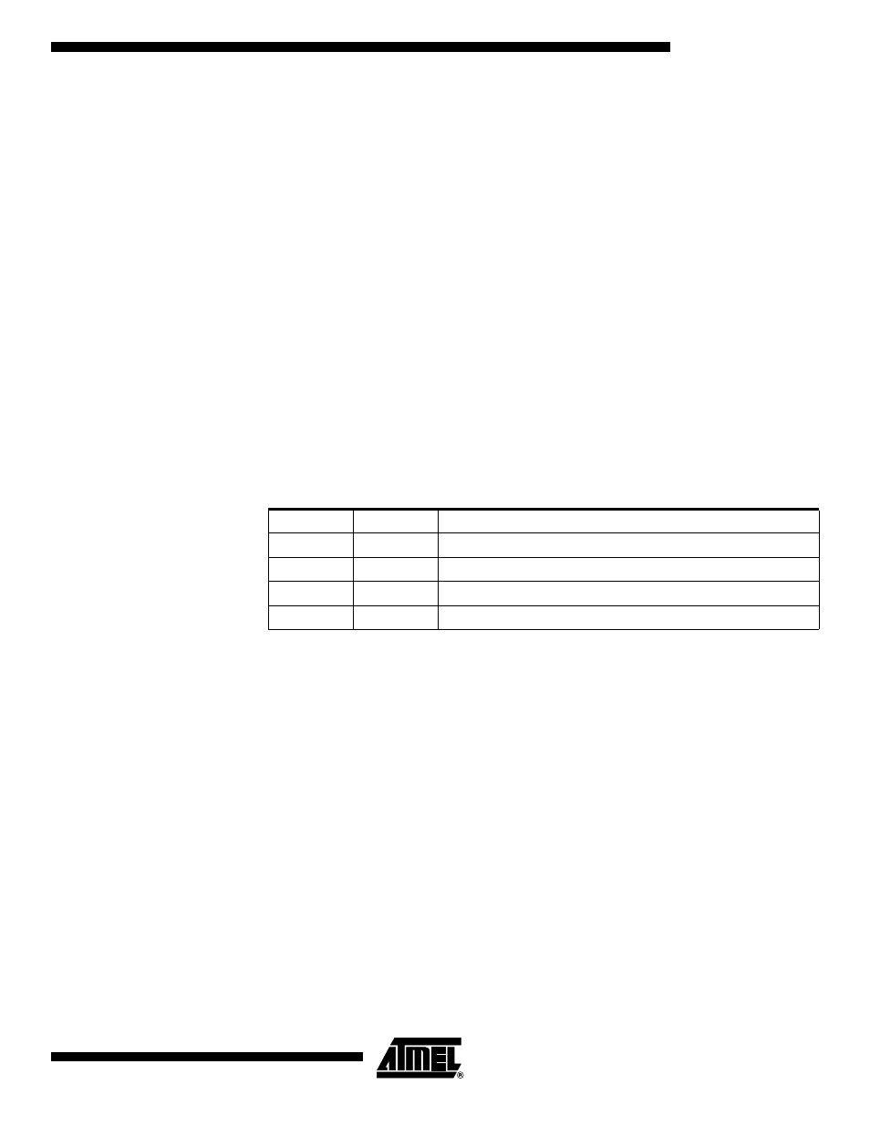
• Bits 1, 0 – ACIS1, ACIS0: Analog Comparator Interrupt Mode Select
These bits determine which comparator events that trigger the Analog Comparator inter-
rupt. The different settings are shown in Table 32.
Note:
1. When changing the ACIS1/ACIS0 bits, the Analog Comparator Interrupt must be dis-
abled by clearing its Interrupt Enable bit in the ACSR Register. Otherwise an interrupt
can occur when the bits are changed.
Table 32. ACIS1/ACIS0 Settings
ACIS1
ACIS0
Interrupt Mode
0
0
Comparator Interrupt on Output Toggle
0
1
Reserved
1
0
Comparator Interrupt on Falling Output Edge
1
1
Comparator Interrupt on Rising Output Edge