Attiny26(l) – Rainbow Electronics ATtiny26L User Manual
Page 49
49
ATtiny26(L)
1477B–AVR–04/02
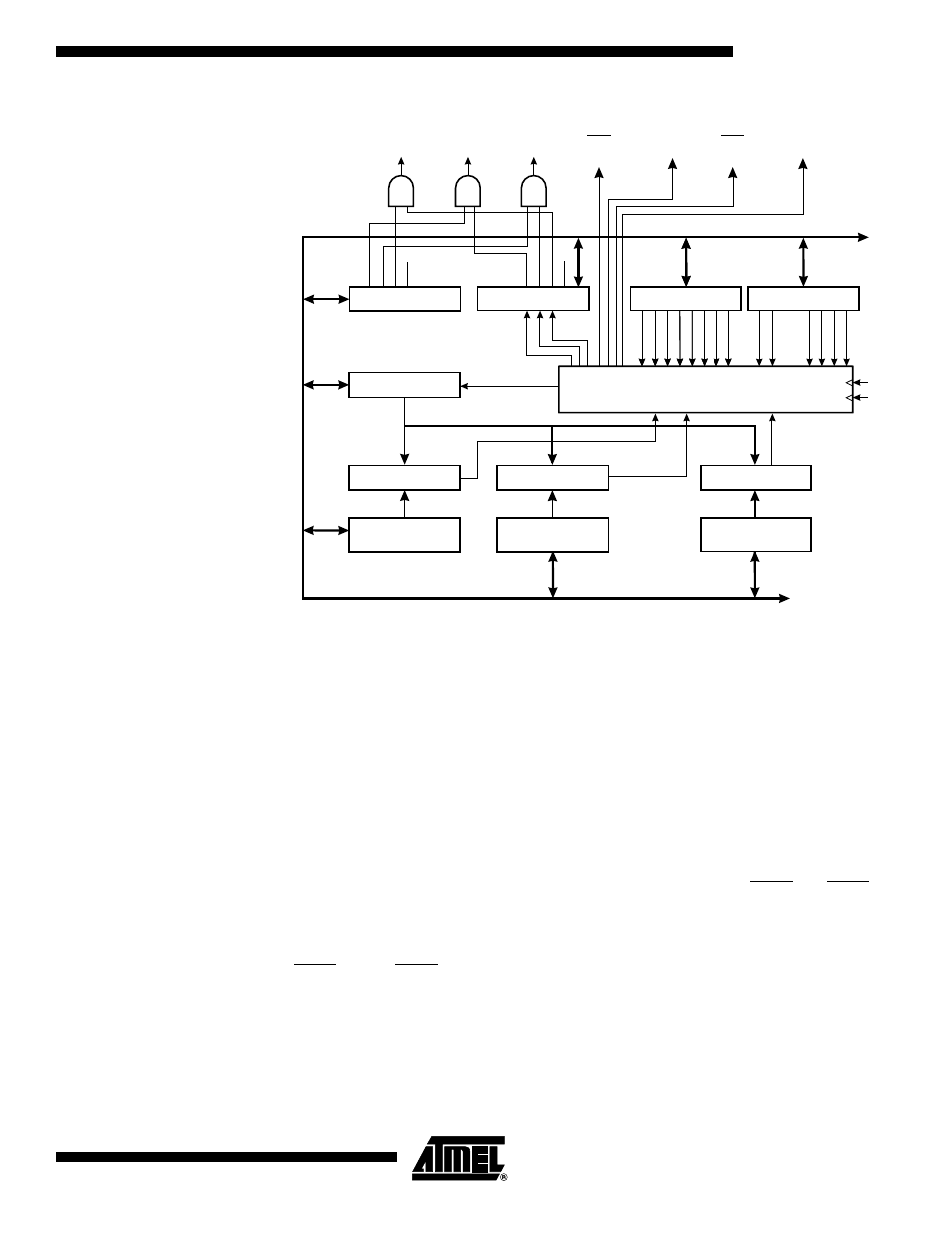
Figure 35. Timer/Counter1 Block Diagram
Three status flags (overflow and compare matches) are found in the Timer/Counter
Interrupt Flag Register – TIFR. Control signals are found in the Timer/Counter Control
Registers TCCR1A and TCCR1B. The interrupt enable/disable settings are found in the
Timer/Counter Interrupt Mask Register – TIMSK.
The Timer/Counter1 contains three Output Compare Registers, OCR1A, OCR1B, and
OCR1C, as the data source to be compared with the Timer/Counter1 contents. In nor-
mal mode the Output Compare functions are operational with all three Output Compare
Registers. OCR1A determines action on the OC1A pin (PB1), and it can generate
Timer1 OC1A interrupt in normal mode and in PWM mode. Likewise, OCR1B deter-
mines action on the OC1B pin (PB3) and it can generate Timer1 OC1B interrupt in
normal mode and in PWM mode. OCR1C holds the Timer/Counter maximum value, i.e.,
the clear on compare match value. An overflow interrupt (TOV1) is generated when
Timer/Counter1 counts from $FF to $00 or from OCR1C to $00. This function is the
same for both normal and PWM mode. The inverted PWM outputs OC1A and OC1B are
not connected in normal mode.
In PWM mode, OCR1A and OCR1B provide the data values against which the
Timer/Counter value is compared. Upon compare match the PWM outputs (OC1A,
OC1A, OC1B, OC1B) are generated. In PWM mode, the Timer/Counter counts up to the
value specified in the Output Compare Register OCR1C and starts again from $00. This
feature allows limiting the counter “full” value to a specified value, lower than $FF.
Together with the many prescaler options, flexible PWM frequency selection is provided.
Table 27 lists clock selection and OCR1C values to obtain PWM frequencies from 20
kHz to 250 kHz in 10 kHz steps and from 250 kHz to 500 kHz in 50 kHz steps. Higher
PWM frequencies can be obtained at the expense of resolution.
8-BIT DATA BUS
TIMER INT. FLAG
REGISTER (TIFR)
TIMER/COUNTER1
8-BIT COMPARATOR
T/C1 OUTPUT
COMPARE REGISTER
TIMER INT. MASK
REGISTER (TIMSK)
TIMER/COUNTER1
(TCNT1)
T/C CLEAR
T/C1 CONTROL
LOGIC
TOV1
OCF1B
OCF1B
TOV1
TOIE0
TOIE1
OCIE1B
OCIE1A
OCF1A
OCF1A
CK
PCK
T/C1 OVER-
FLOW IRQ
T/C1 COMPARE
MATCH B IRQ
OC1A
(PB1)
T/C1 COMPARE
MATCH A IRQ
T/C CONTROL
REGISTER 1 (TCCR1A)
COM1B1
PWM1A
PWM1B
COM1B0
FOC1A
FOC1B
(OCR1A)
(OCR1B)
(OCR1C)
8-BIT COMPARATOR
T/C1 OUTPUT
COMPARE REGISTER
TOV0
COM1A1
COM1A0
T/C CONTROL
REGISTER 1 (TCCR1A)
OC1A
(PB0)
OC1B
(PB3)
OC1B
(PB2)
8-BIT COMPARATOR
T/C1 OUTPUT
COMPARE REGISTER
T/C CONTROL
REGISTER 1 (TCCR1B)
CS12
PSR1
CS11
CS10
CS13
CTC1