Mlim-2; frequency input application – Omega Vehicle Security OMP-MODL User Manual
Page 58
3... I
NTERFACE
M
ODULES
U
SING
T
HE
OMP-MODL
3-34
CAUTION: Note that a direct connection exists between
the common (-) terminal on all four channels of the MLIM-
2 (
Figure 3... -22). When connecting to multiple event or
counter signal sources sharing a common ground or
reference, insure that the source’s ground or reference is
connected to the terminal strip `common’ terminal to
prevent shorting out of the source signal and possible
damage to the MLIM-2.
For most counter and event applications, shielding is not necessary due to
the relatively low input impedance of the channel and the high noise
immunity of the MLIM-2 channel input.
MLIM-2; FREQUENCY INPUT APPLICATION
An MLIM-2 channel configured as a Frequency type input can measure input
frequencies ranging from 5Hz to in excess of 20KHz. The channel will accurately
measure frequencies of sine, square, or sine approximating input waveforms with
peak to peak amplitudes of 300mVDC to 15VDC. Channel input impedance is
greater than 30K ohm within the specified input range.
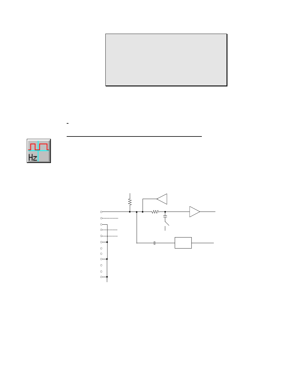
The MLIM-2 incorporates an AC coupled front-end amplifier for use with low
amplitude signals ( see AMP inFigure 3... -22).
Figure 3... -
21:
Frequency
icon
(MLIM-2)
A
B
COM
C
D
COM
N/C
COM
COM
N/C
N/C
N/C
V+
R1
C1
Debounce RC
Current Limited Output Driver
Count / Event Signal
Amplified Frequency
AMP
Software Controlled
Debounce Circuit
HyperLogger
Circuit Ground
HLIM-2 Terminal Strip Connections
ML059
Figure 3... -22: Simplified schematic of MLIM-2 input channel (single
channel shown)