Dc current, Module installation, I/o module layer requirements / limitations – Omega Vehicle Security OMP-MODL User Manual
Page 44
3... I
NTERFACE
M
ODULES
U
SING
T
HE
OMP-MODL
3-20
DC Current:
Full Scale (FS) ranges:
Input resistance for all current ranges is a 100 ohm precision shunt.
Module Installation:
Refer to the Installation Section earlier in this chapter for detailed installation
instructions of the Interface Module onto the System Base.
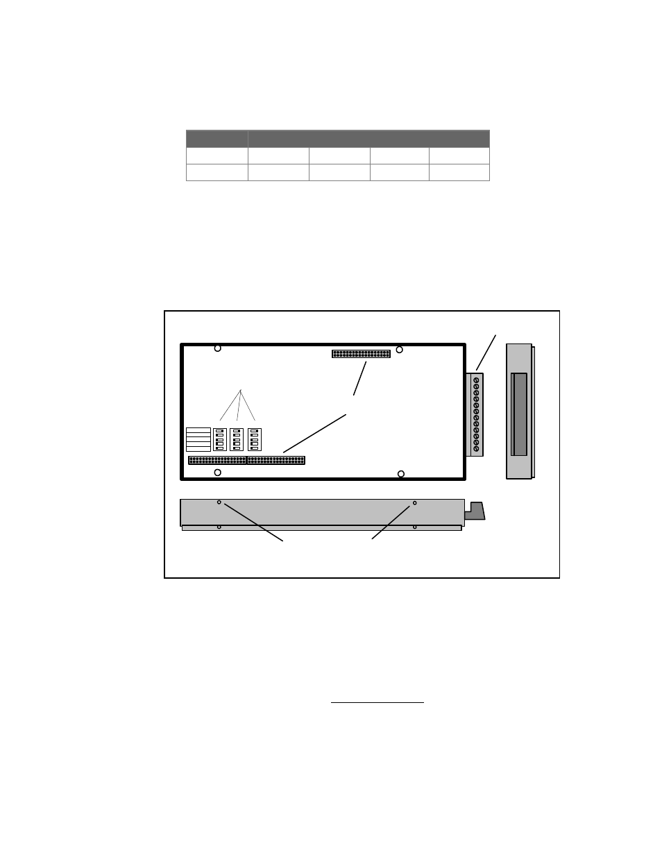
I/O Module Layer Requirements / Limitations:
The MLIM-1 module can be installed in any of the five I/O Module positions
(Figure 3... -4). The module layer address must be set on the module to
correspond to the layer position into which the module is installed.
This address is programmed into the module through the use of the three
Module Address Switch banks (Figure 3... -9). Each switch bank contains 5
switches. Note the marking on the circuit board identifying address rows for
Module Layers 2 through 5. Set one switch in each of the 3 banks ON
corresponding to a module layer determined above. Each switch bank
should have only ONE switch ON and the other four switches OFF.
Icon
Full Scale Input Ranges
mA-LO
+/-200uA
+/-400uA
+/-500uA
+/-1.0mA
+/-2.0mA
+/-11 mA
+/-22mA
Table 3... -3: DC Current input ranges
Inter-Module Connection bus
I/O Wiring Terminal
Strip
Side Retaining Screw holes
ml051
Module 3
Module 2
Module 4
Module 5
Module 6
OFF - ON
OFF - ON
OFF - ON
Module Address (Layer) Switches
Figure 3... -9: MLIM-1 Module Address Switches