Lcd message – Omega Vehicle Security OMP-MODL User Manual
Page 198
11.. . A
PPENDIX
A: M
ASTER
I
CON
F
ILE
R
EFERENCE
U
SING
T
HE
OMP-MODL
11-36
LCD MESSAGE
O
UTPUT
I
CON
FUNCTION:
User programmed messages can be displayed on the LCD (liquid crystal display) on the
front panel of the OMP-MODL System Base. The LCD Message icon provides for User
entry of a two-line message for display when the icon input is TRUE.
INPUTS:
Data/Logic Signal: Logic type. True input turns message ON. False input turns
message display OFF. Optionally, use the Latch icon in front of the LCD
Message icon to latch the message ON upon receipt of a momentary True
input.
Update Clock:
None
Enable:
Processing of icon is allowed when Enable pin is unconnected or
when connected and Enable signal is TRUE.
OUTPUTS:
Output Signal:
Hardware output (to LCD display) only. No output terminal shown
on icon for Program Net connections.
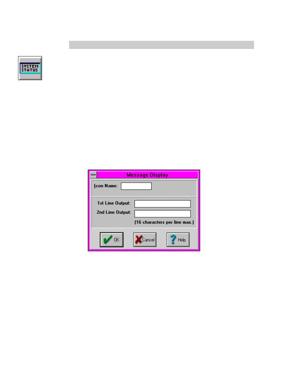
ICON CONFIGURATION DIALOG BOX:
CONFIGURATION OPTIONS:
Icon Name: Specify the label for the icon. This name will show directly under the icon
within the Program Net.
First / Second Line Output: Two text boxes are provided for User entry of text to be
displayed on the LCD when the Input is TRUE. Up to 16 characters can be
entered on each line.
APPLICATION CONSIDERATIONS:
When the LCD icon is activated (ie its input is TRUE), the programmed message is
displayed on the OMP-MODL LCD. If a second (different) message is activated the
second message will be displayed on the LCD and the first message will be maintained
on a queue of active messages. This queue of messages can be reviewed via the OMP-
MODL front panel Next / Select buttons menu Display Status Messages or via a Status
Query from within the HyperComm Window.