Warning – Omega Vehicle Security OMP-MODL User Manual
Page 255
11.. . A
PPENDIX
A: M
ASTER
I
CON
R
EFERENCE
U
SING THE
OMP-MODL
11-93
WARNING
F
UNCTION
I
CON
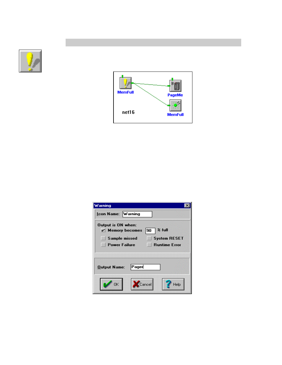
The Warning icon outputs a True Logic signal while any of five User selected system
conditions are true. Multiple Warning icons can be used in a Program Net to initiate
alarming or other action upon different conditions. The following example illustrates
activation of a Page (and front panel LED) if the Logger memory fills to 90%.
INPUTS:
Data/Logic Signal: None, internal system status only. No terminals shown for icon
connections in Net.
Enable:
Processing of the icon is allowed when the Enable pin is unconnected or
when connected and Enable signal is TRUE.
OUTPUTS:
Output Signal:
Logic (True/False). Output is TRUE only while any of the five
conditions are true. A Latch icon can be connected to the Output of this
icon if a latching function is desired.
ICON CONFIGURATION DIALOG BOX: