Omega Vehicle Security OMP-MODL User Manual
Page 168
11.. . A
PPENDIX
A: M
ASTER
I
CON
F
ILE
R
EFERENCE
U
SING
T
HE
OMP-MODL
11-6
S
UPPLY
V
OLTAGE
(V
BATT
) I
NPUT
I
CON
(S
YSTEM
B
ASE
)
FUNCTION:
Used to take readings of the OMP-MODL internal Supply Voltage. If internal batteries are
installed in the OMP-MODL and an external power supply is also connected, the output
value will be the higher of the two.
The Supply Voltage output from this icon is representative of the voltage measured at an
internal node on the power supply circuitry. Displayed battery voltage is the voltage of the
internal batteries . External supply voltage will be approximately 2 volts higher than
indicated. If the Input Range Jumper (see MLCPU-1 section) is set to HI, the External
supply voltage will be approximately 3.5 volts higher than indicated.
INPUTS:
Hardware:
No signal input shown on icon for Program Net connections. Input
signal comes from system voltage measurement.
Update Clock:
Output is updated with new reading upon each Update Clock pulse
when Enable input is unconnected or HI.
Enable:
Processing of icon is allowed when Enable pin is unconnected or
connected and Enable signal is TRUE.
OUTPUTS:
Output Signal:
Data type signal. The Units of the output are Volts
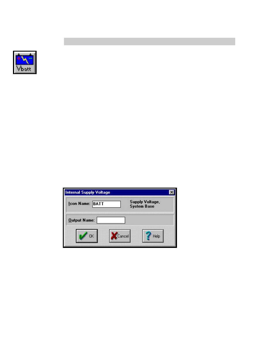
ICON CONFIGURATION DIALOG BOX:
CONFIGURATION OPTIONS:
Icon Name:
Specify the label for the icon. This name will show directly under
the icon within the Program Net.
Output Name:
Specify the label for the Output. This name will show directly
under the Output terminal within the Program Net.