Mlcpu-1 m, Overview, User interface indicators and buttons – Omega Vehicle Security OMP-MODL User Manual
Page 12: Main power switch, Odule
2... OMP-MODL System Base
Using the OMP-MODL
2-3
TIP: For applications utilizing loggers equipped with a large number of
Interface Modules, the stack can become rather tall. In these
applications, side plate mounting may be desired. Contact LBI for
details on the side mounting bracket..
MLCPU-1 M
ODULE
Overview
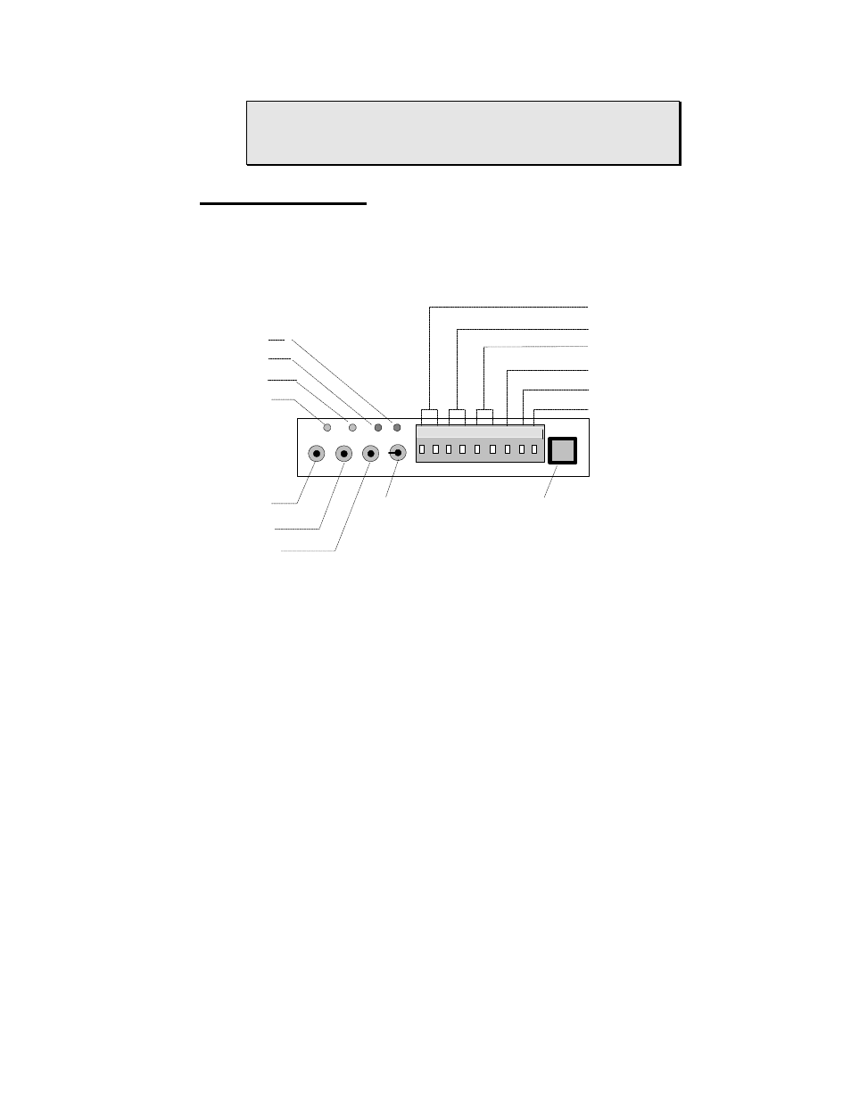
The MLCPU-1 module contains the microprocessor, memory, power
supplies, GPDI input circuitry, alarm output circuitry, User push buttons and
status indicators. Various components in this module are identified in Figure
2... -3. This module is required in all OMP-MODL systems.
User Interface Indicators and Buttons
An array of LED indicators and buttons are available at one end of the
MLCPU-1. Identification and function follows:
Main Power Switch:
A small recessed toggle switch controls the power to the logger.
Using a pencil or other small object, flip the switch side to side to
turn power ON/OFF. Upon turning power ON, after a short delay,
the Feedback LED (see following) will blink 5 times indicating that
the unit has sequenced through a power-up reset and is operative,
ready to accept commands.
STOP
RESET
ENABLE
POWER
SERIAL PORT
RELAY 2
RELAY 1
STATUS
FEEDBACK
EXTERNAL POWER
RELAY R1
RELAY R2
+5V
TTL
GND
1
2
3
4
5
6
7
8
9
Figure 2... -3: MLCPU-1 Module (end view)