Figure 34, Attaching the bip ground cable – Nortel Networks 8010co User Manual
Page 51
Chapter 2 Installation
51
Installing the Breaker Interface Panel for the Ethernet Routing Switch 8010co Chassis
6
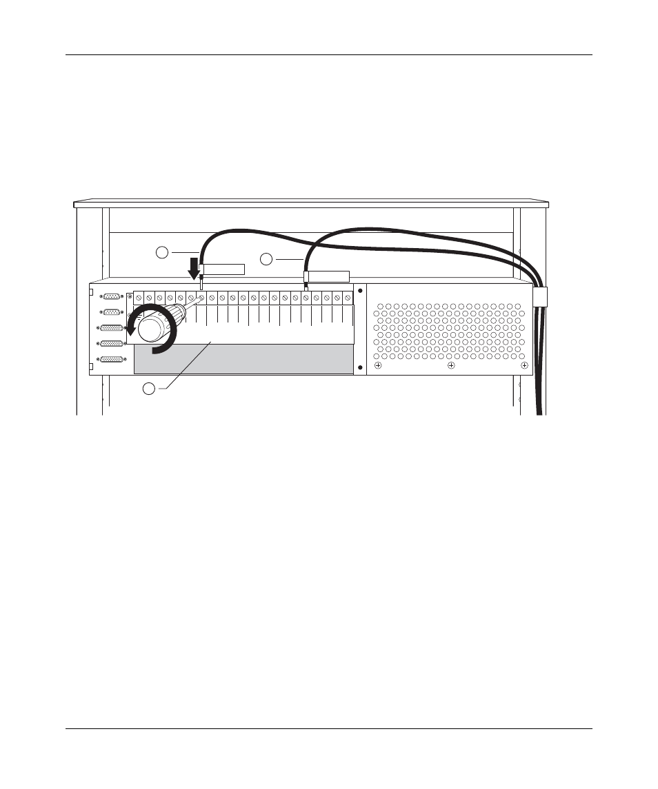
Attach one end of the BIP ground cable to the power terminal block
(
a
Loosen the power terminal block screw just enough to insert the ground
cable lead (item 1 in
).
b
Insert the lead and tighten the screw securely.
Figure 34 Attaching the BIP ground cable
7
Route the other end of the BIP ground cable to the rack grounding strip near
the base of the rack (see
).
Use a 7/16-inch hex wrench to fasten the hardware in the correct order.
8
Go to the next section,
“Connecting DC input power feeds to the BIP” on
.
3 2
PS (+)
Lower Shelf
PS (+)
Upper Shelf
PS (-)
Lower Shelf
PS (-)
Upper Shelf
A/B Input Feed
Returns
– 48 VDC
A/B Input Feeds
1 3 2 1
3 2 1 3 2 1
A
2
A
1
B
1
B
2
3
+DC PS1 Upper
-DC PS1 Upper
1
2
1 = Positive lead wire from power
supply 1, upper shelf
3 = Power terminal block label