Figure 33 – Nortel Networks 8010co User Manual
Page 50
50
Chapter 2 Installation
312755-G Rev 00
4
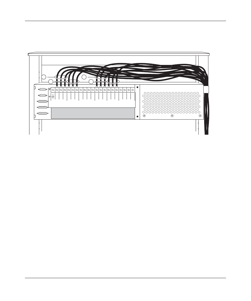
Repeat steps
through
for each remaining power supply in your
configuration (
Figure 33 Upper and lower shelf power cables connected to the BIP
5
Locate the BIP ground cable (see
).
10394FA
3 2
PS (+)
Lower Shelf
PS (+)
Upper Shelf
PS (-)
Lower Shelf
PS (-)
Upper Shelf
A/B Input Feed
Returns
– 48 VDC
A/B Input Feeds
1 3 2 1
3 2 1 3 2 1
A
2
A
1
B
1
B
2
1 = Positive lead wires
(lower shelf power supplies)
2 = Positive lead wires
(upper shelf power supplies)
3 = Negative lead wires
(lower shelf power supplies)
4 = Negative lead wires
(upper shelf power supplies)
1
2
3
4