Front panel, Shelf circuit breakers (upper and lower shelves), Figure 2 – Nortel Networks 8010co User Manual
Page 20: Front panel components, Figure 2 sho ws the bip front panel components, Or off
20
Chapter 1 Overview
312755-G Rev 00
Front panel
shows the BIP front panel components.
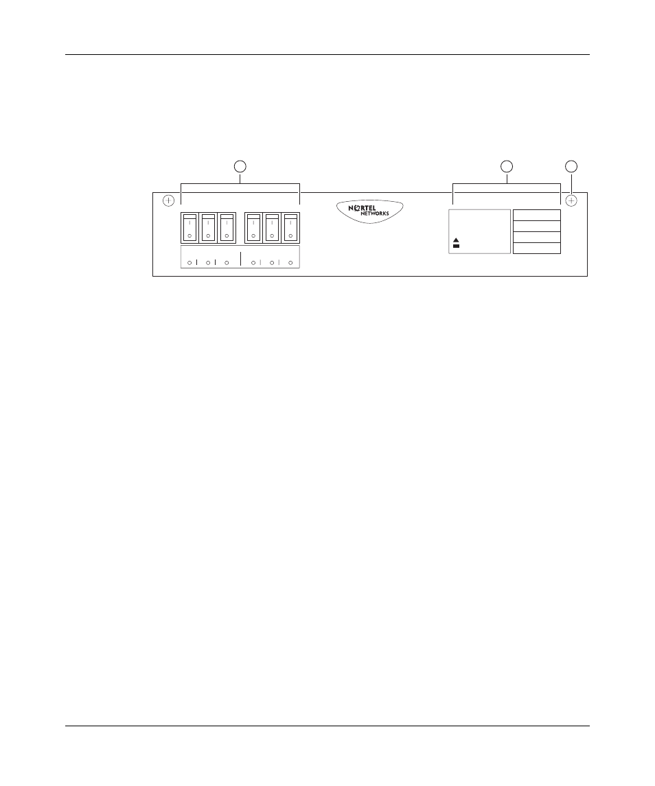
Figure 2 Front panel components
Shelf circuit breakers (upper and lower shelves)
Two groups of three circuit breakers provide input power to the power supplies for
the upper and lower shelf 8010co chassis (
•
The first group, labeled “Upper Shelf,” provides input power to the upper
shelf power supplies.
•
The second group, labeled “Lower Shelf,” provides input power to the lower
shelf power supplies.
If a power supply over current condition occurs, the associated circuit breaker
trips and indicates the fault by lighting the associated circuit breaker’s LED (red).
Each of the six circuit breakers is current limited to 30 amperes @80 volts direct
current. The circuit breakers are designed with internal auxiliary switches to
provide fault indications to the alarm module and to the associated circuit breaker
LEDs on the front panel. The alarm module reports circuit breaker fault conditions
by lighting the MAJOR indicator on the Alarm Module display panel.
No alarm is generated to the alarm module when the circuit breaker is manually
switched on (
|
) or off (
O
).
10376EB
1 = Shelf circuit breakers (upper/lower shelves)
2 = Alarm module display panel
3 = Front-panel locking screws (x2)
3
1
2
POWER
CRITICAL
MAJOR
MINOR
Upper Shelf
1
2
3
1
2
3
Lower Shelf
Alarm Module