Front panel locking screws, Back panel, Shelf alarm connectors (upper and lower shelves) – Nortel Networks 8010co User Manual
Page 24: Figure 5, Back panel components
24
Chapter 1 Overview
312755-G Rev 00
Front panel locking screws
The front panel locking screws allow you to open the front panel to access the
alarm module. The alarm module contains jumpers that you use to configure your
system alarm parameters.
For information about configuring your system alarm parameters, see
.
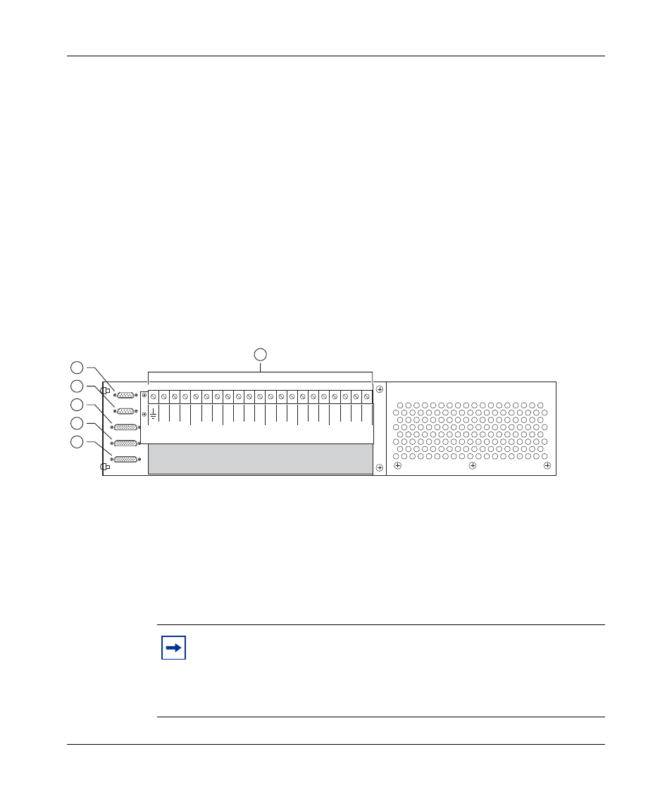
Back panel
shows the BIP back panel configuration (plastic back cover not shown).
Descriptions of the back panel components follow the figure.
Figure 5 Back panel components
Shelf alarm connectors (upper and lower shelves)
The shelf alarm connectors allow you to configure the BIP to control more than
one 8010co chassis.
Note: The BIP ships from the factory with default alarm configurations
set for a single chassis in the lower shelf of the rack. If you install a
second chassis, you must also configure the jumper on the alarm module
to support that configuration.
See “Accessing the alarm module” on
for information about jumper settings for your configuration.
10367EA
1 = J1 Upper shelf alarm connector
2 = J2 Lower shelf alarm connector
3 = J3 Central office alarm "in"
4 = J4 Central office alarm "out"
5 = J5 Standalone office alarm connector
6 = TB1 Power terminal block
3 2
PS (+)
Lower Shelf
PS (+)
Upper Shelf
PS (-)
Lower Shelf
PS (-)
Upper Shelf
A/B Input Feed
Returns
– 48 VDC
A/B Input Feeds
1 3 2 1
3 2 1 3 2 1
A
2
A
1
B
1
B
2
6
1
2
3
4
5