Connecting the power supply cables to the bip, Figure 32, Attaching power supply cable leads to the bip – Nortel Networks 8010co User Manual
Page 49
Chapter 2 Installation
49
Installing the Breaker Interface Panel for the Ethernet Routing Switch 8010co Chassis
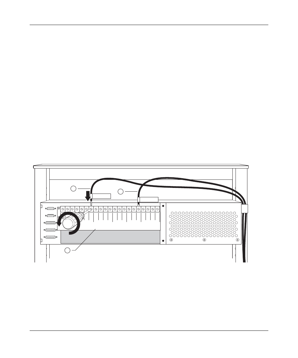
Connecting the power supply cables to the BIP
To connect the power supply cables to the BIP:
1
Locate one of the power supply cables.
2
Match the labeled tag on the power supply cable with the correct location on
the power terminal block (
The power terminal block label indicates a location for the positive and
negative power supply leads for both the upper shelf and lower shelf power
supplies.
3
Loosen the appropriate power terminal block screw, and then insert the cable
lead (item 1 in
). Tighten the screw securely.
shows the negative cable lead from power supply 1 in the
upper shelf correctly connected to the power terminal block.
Figure 32 Attaching power supply cable leads to the BIP
10393FA
3 2
PS (+)
Lower Shelf
PS (+)
Upper Shelf
PS (-)
Lower Shelf
PS (-)
Upper Shelf
A/B Input Feed
Returns
– 48 VDC
A/B Input Feeds
1 3 2 1
3 2 1 3 2 1
A
2
A
1
B
1
B
2
3
+DC PS1 Upper
-DC PS1 Upper
1
2
1 = Positive lead wire from power
supply 1, upper shelf
2 = Negative lead wire from power
supply 1, upper shelf
3 = Power terminal block label