Figure 6, Shelf alarm connections (upper and lower shelves) – Nortel Networks 8010co User Manual
Page 25
Chapter 1 Overview
25
Installing the Breaker Interface Panel for the Ethernet Routing Switch 8010co Chassis
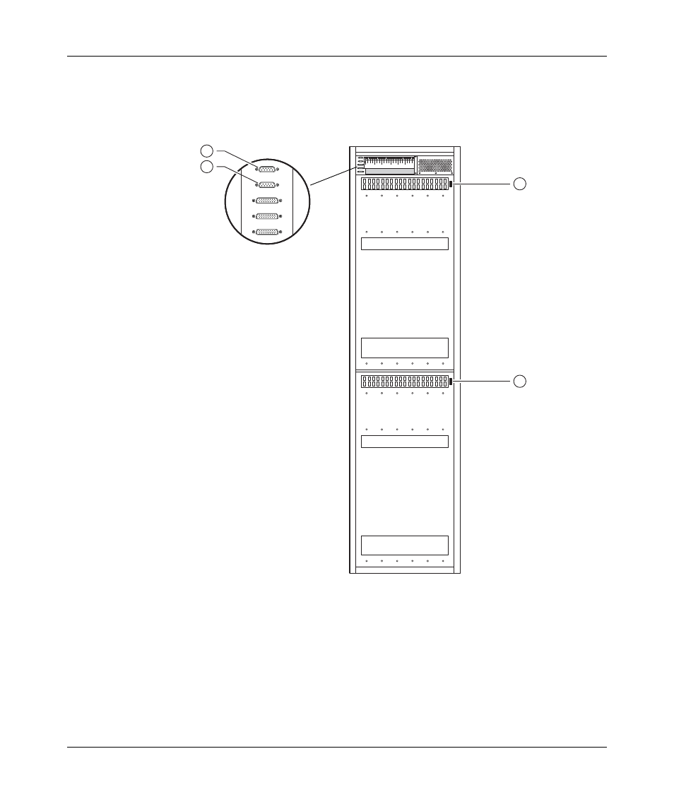
shows the location of the shelf alarm connectors on the BIP and on two
8010co chassis (upper and lower shelves).
Figure 6 Shelf alarm connections (upper and lower shelves)
1 = J1 (BIP upper shelf alarm connector)
2 = J2 (BIP lower shelf alarm connector)
3 = Upper shelf chassis alarm connector "out"
4 = Lower shelf chassis alarm connector "out"
1
2
3
4
J1
J2
J3
J4
J5
10380EA