Figure 31, Rack grounding strip example – Nortel Networks 8010co User Manual
Page 48
48
Chapter 2 Installation
312755-G Rev 00
5
Route the remaining (black) power supply cables from the back of the lower
and upper shelf chassis to the back panel of the BIP, loosely fastening them
with tie-wraps along the path.
6
Loosely support the power supply cables with tie-wraps above the BIP power
terminal block.
7
Proceed to,
“Connecting the ground cables to the rack grounding strip
.”
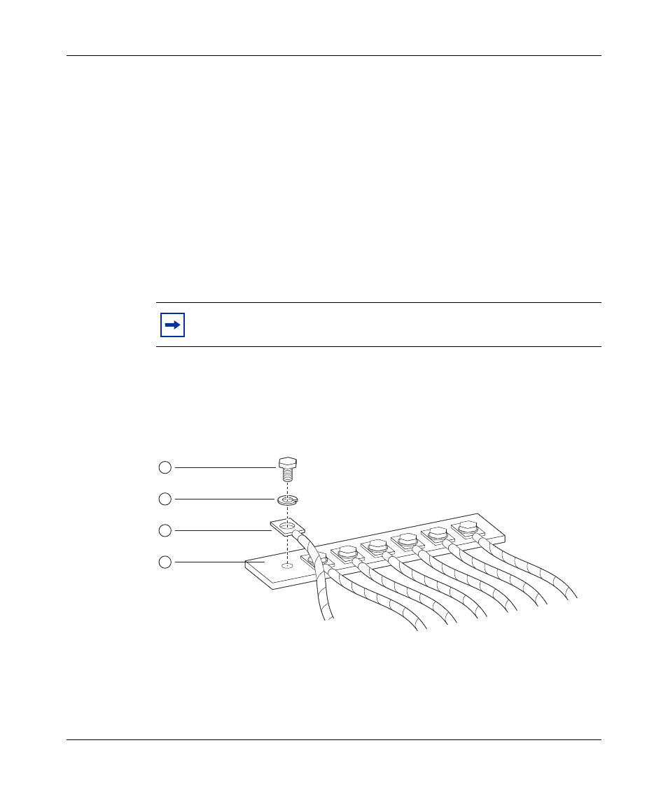
Connecting the ground cables to the rack grounding strip
To connect the power supply ground cables to the rack grounding strip:
1
Locate the rack grounding strip at the back base of the rack (
).
2
Attach the lug ends of the power supply ground cables to the rack grounding
strip (
).
Use a 7/16-inch hex wrench to fasten the hardware in the correct order.
Figure 31 Rack grounding strip example
3
Proceed to
“Connecting the power supply cables to the BIP” on page 49
.
shows an example of a rack grounding strip. Your rack
grounding strip can look different than the one shown in this example.
10433FA
1
2
3
4
1 = Hex head bolt
2 = Lock washer
3 = Ground crimp lug
4 = Rack grounding strip