Figure 27, Attaching the negative lead, Figure 28 – Nortel Networks 8010co User Manual
Page 45: Dc +dc
Chapter 2 Installation
45
Installing the Breaker Interface Panel for the Ethernet Routing Switch 8010co Chassis
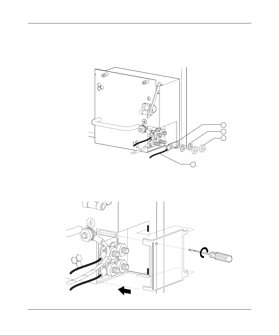
10 Attach the lug end of a 125-inch power supply cable to the negative terminal
on the power supply (
).
Use a 7/16-inch hex wrench to fasten the hardware in the correct order.
Figure 27 Attaching the negative lead
11 Replace the plastic safety cover on the power supply (
).
Figure 28 Replacing the plastic safety cover on the power supply
+DC
-DC
4
3
2
1
1 = Two-hole crimp lug
2 = Lock washer (x 2)
3 = Hex nut (x 2)
4 = Negative lead wire
10430FA
-DC
+DC
10431FA