Alarm module display panel, Figure 4, Table 1 – Nortel Networks 8010co User Manual
Page 22: Alarm module display leds, See table 1 for a description of the leds
22
Chapter 1 Overview
312755-G Rev 00
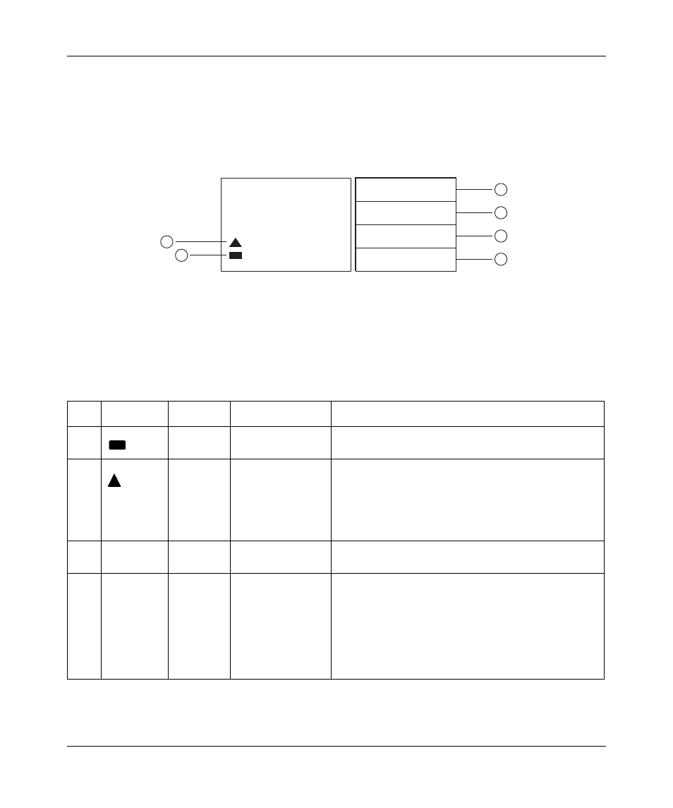
Alarm module display panel
The alarm module display panel (
), located on the BIP front panel,
provides visual status indications for one or two 8010co chassis in a single rack.
Figure 4 Alarm module display panel
for a description of the LEDs.
Table 1 Alarm module display LEDs
Item
Label/Icon
Type
Color/State
Description
1
LED
Green/On steady
Shelf alarm cable validation LED—The alarm cables
are properly connected to the shelves.
2
LED
Red/On steady
Shelf alarm cable fault LED—The shelf alarm cables
are missing, not secured, or the shelf alarm jumpers
are not configured properly (see
). This fault condition also lights
the MINOR fault indicator (see Minor fault description
in this table).
3
POWER
Indicator
White/On steady
Power indicator—The external DC power is available
to the BIP.
4
CRITICAL
Indicator
Red/On steady
Critical fault indicator—Indicates that a severe
service-affecting condition has occurred that requires
immediate corrective action. Common causes for this
type of fault condition include:
•
Line card failure
•
Temperature fault
•
CPU fault when only one CPU is installed
10377EA
1 = Shelf alarm cable validation LED
2 = Shelf alarm cable fault LED
3 = POWER indicator
4 = CRITICAL fault indicator
POWER
CRITICAL
MAJOR
MINOR
Alarm Module
1
2
3
4
5
6
5 = MAJOR fault indicator
6 = MINOR fault indicator