Figure 2-8. fp-3000 power connector pinout, Led indicators, Power-on self test (post) – National Instruments FP-3000 User Manual
Page 31: Led indicators -13, Power-on self test (post) -13
Chapter 2
Installation and Configuration
© National Instruments Corporation
2-13
FieldPoint FP-3000 User Manual
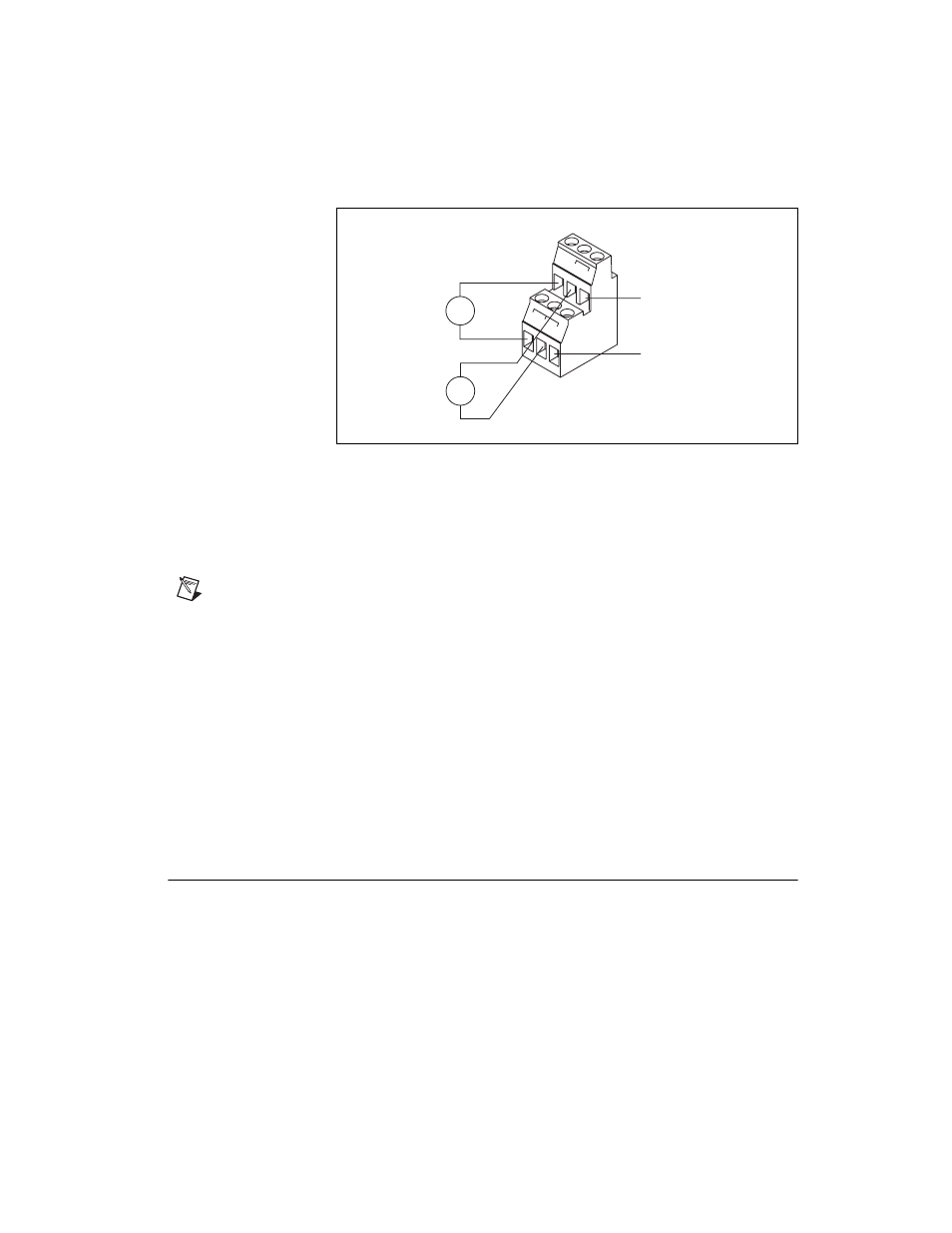
Figure 2-8. FP-3000 Power Connector Pinout
Connect the primary power supply to the center V and C pair with the
positive and negative wires on your power cable in the V and C terminals,
respectively. You can connect an optional backup power supply to the left
V and C pair.
Note
The FP-3000 will automatically use the power supply with the highest voltage. Do
not use a battery backup with a higher voltage than the primary supply. In this case, the
device will run off of the battery until the battery’s voltage level drops below that of the
primary power supply.
The right V and C pair provides a convenient means of connecting power
to the V and C terminals of a terminal base. Figure 2-8 shows this optional
connection.
If your field I/O devices need to be powered separately, you can use the
terminals provided on each terminal base for such power supply
connections. Refer to the documentation that came with your terminal base
and I/O module for more information on powering your field I/O devices.
LED Indicators
Power-On Self Test (POST)
The power-on self test (POST) is a test suite that the FP-3000 performs at
power up to verify its own operational status. The test takes several
seconds. The test is non-invasive and therefore does not affect the operation
of the network, nor does it affect any of your field wiring connected to the
terminal bases in the bank.
v
v
v
c c
c
11-30 VDC
Backup Power
Supply
(optional)
+
–
+
–
11-30 VDC
Primary Power
Supply
V
C
To adjacent terminal base
(if option 3 for powering
output is chosen)