Laser beta lasermike LS8000-3 User Manual
Page 58
LaserSpeed 8000-3 Instruction Handbook
Interfacing with the LS8000-3
Part No. 93463 / Drawing No. 0921-01561
Page 58 of 221
Revision A (Sep 2007)
Analog speed data can be obtained in a 0–2 V format. An optional selectable
voltage/current output module which will convert the 0–2 V signal supplied by
the gauge to all of the common voltage/current levels is available. The analog
output indicates speed but not direction.
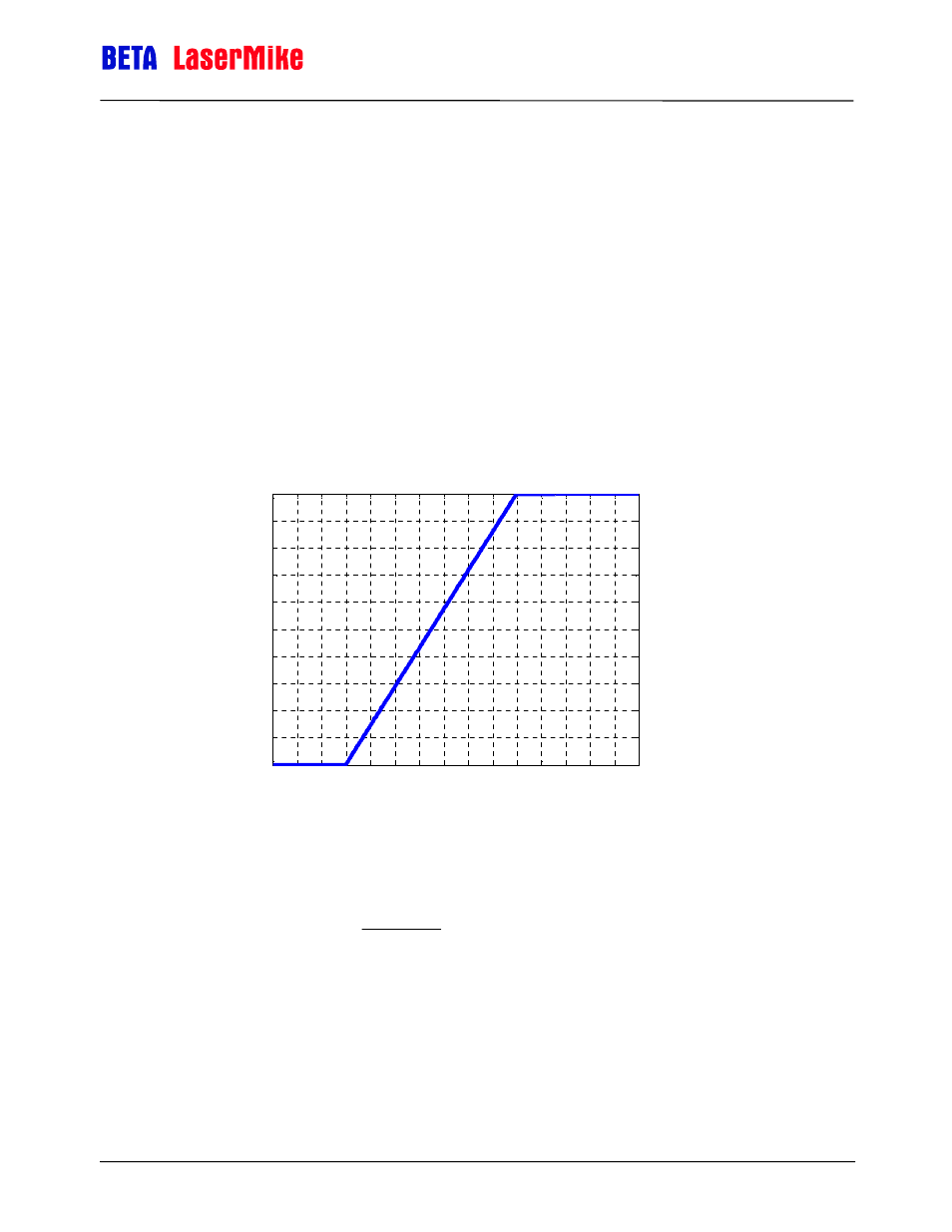
There are two configuration settings that affect the operation of the analog
output. The Analog Zero Scale Velocity sets the speed where the analog
output reaches 0V. The Analog Full Scale Velocity sets the speed where the
analog output reaches 2V. At speeds between these two settings, the analog
output increases linearly as the speed increases from the Analog Zero Scale
Velocity to the Analog Full Scale Velocity.
Example: If the Analog Zero Scale Velocity were set to 30 m/min, and the
Analog Full Scale Velocity were set to 100 m/min, the analog output would
behave as shown in the following figure.
The LS8000's measured speed can be calculated from the analog output
voltage with the following equation:
(
)
⎪
⎪
⎩
⎪
⎪
⎨
⎧
=
=
<
<
≥
≤
+
−
×
=
V
Voltage
V
Voltage
V
Voltage
V
when
V
V
V
V
V
Voltage
Speed
FS
ZS
ZS
ZS
FS
2
0
2
0
2
where:
V
FS
= Analog Full Scale Velocity
V
ZS
= Analog Zero Scale Velocity
0
10
20
30
40
50
60
70
80
90 100 110 120 130 140 150
0
0.2
0.4
0.6
0.8
1
1.2
1.4
1.6
1.8
2
Measured Velocity
A
nal
og
O
ut
put
/
V
ol
ts
Analog Output vs Measured Velocity with V
ZS
= 30 and V
FS
= 100