Connecting to outputs – Laser beta lasermike LS8000-3 User Manual
Page 25
LaserSpeed 8000-3 Instruction Handbook
Installing the System
Part No. 93463 / Drawing No. 0921-01561
Page 25 of 221
Revision A (Sep 2007)
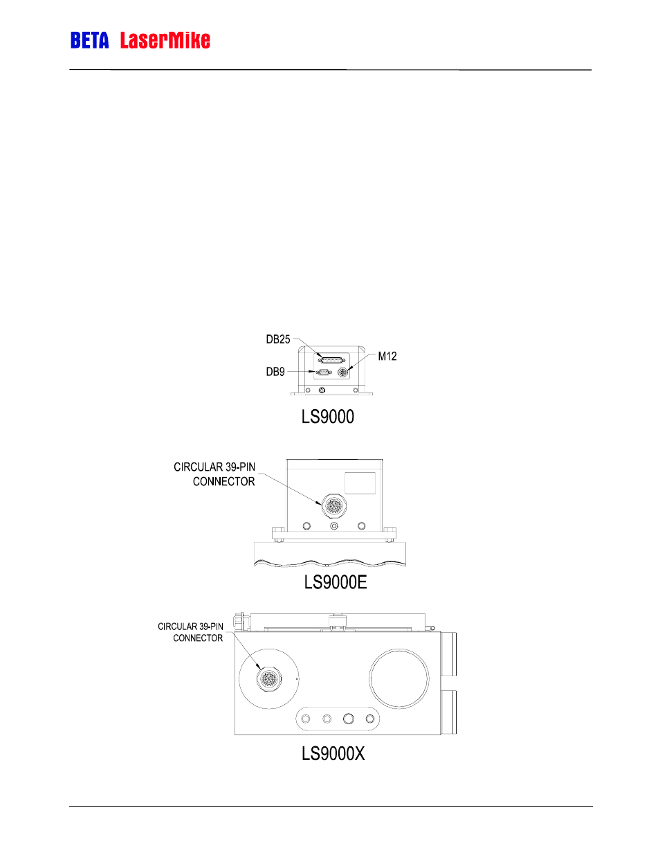
Connecting to Outputs
On the LS8000-3 model, the outputs of the gauge are contained on the 9-pin
and 25-pin D-sub connectors, and the M12 D-Coded Ethernet connector. On
the LS8000-3E and LS8000-3X, all outputs are contained on a 39-pin circular
connector. Their pin values are shown in the following tables. Each signal is
explained in detail in the Interfacing with the LS8000-3 section.
Note: In order for the LS8000-3 to be operational, pins 16 and 17 must
be connected to signal ground. These signals operate the internal
laser shutter and the laser interlock. When these connections are
open, the laser will not turn on and the shutter will not open. You
must provide the correct signals to operate the gauge.