Data transport connector (zone 2), 17 data transport connector (zone 2) j23, 2 data transport connector (zone 2) – Intel NetStructure MPCBL0001 User Manual
Page 85
Technical Product Specification
85
Order #273817
Intel NetStructure
®
MPCBL0001 High Performance Single Board Computer
Contents
4.1.2
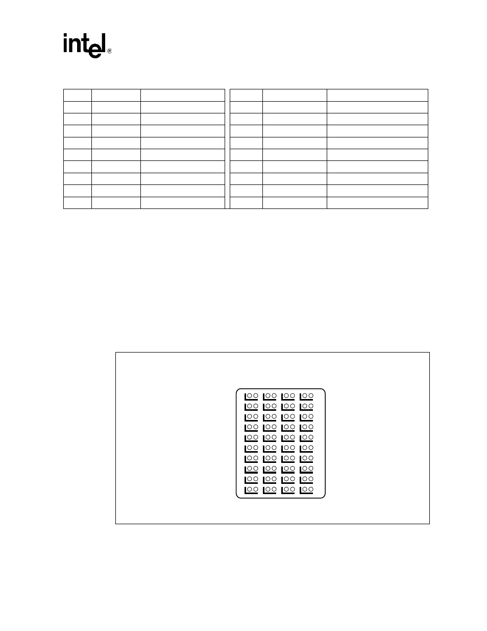
Data Transport Connector (Zone 2)
Zone 2 consists of one 120-pin HM-Zd connector, labeled P23, with 40 differential pairs. This data
transport connector provides the following signals:
•
Two 10/100/1000Base-T/TX Ethernet base fabric channels (four differential signal pairs each,
16 signals total).
•
Two 2 Gbit Fibre Channel ports on the extended fabric (two differential signal pairs each, eight
signals total).
The connector used is AMP/Tyco part number 1469001-1, Intel part number A66621-001.
Figure 17, “Data Transport Connector (Zone 2) J23” on page 85
shows a face view of the
connector.
The following naming convention describes the signals on this connector. Signal direction is
defined from the perspective of MPCBL0001.
8
GA3
Geographic Addr Bit 3
25
EMI_GND
EMI Chassis Ground
9
GA4
Geographic Addr Bit 4
26
LOGIC_GND
Gnd Ref for Card Logic
10
GA5
Geographic Addr Bit 5
27
ENABLE_B
Enb DC-DC conv, B Feed
11
GA6
Geographic Addr Bit 6
28
VRTN_A
-48 V Return, Feed A
12
GA7/P
Geo Adr Bit 7 (Odd Parity)
29
VRTN_B
-48 V Return, Feed B
13
IPMB_CLK_A
IPMB Bus A Clock
30
- 48 V_EARLY_A
-48 V In, Feed A Precharge
14
IPMB_DAT_A
IPMB Bus A Data
31
-48 V_EARLY_B
-48 V In, Feed B Precharge
15
IPMB_CLK_B
IPMB Bus B Clock
32
ENABLE_A
Enb DC-DC conv, A Feed
16
IPMB_DAT_B
IPMB Bus B Data
33
-48V_A
-48 V Input, Feed A
17
Unused
No Connect
34
-48V_B
-48 V Input, Feed B
Table 45.
Power Distribution Connector (Zone 1) P10 Pin Assignments
Figure 17.
Data Transport Connector (Zone 2) J23
B0899-01
1
HG
FE
DC
BA
HG
FG
DG
BG
2
3
4
5
6
7
8
9
10