31 network link leds 32 network speed leds, 6 network link/speed leds, 7 ethernet controller port state leds – Intel NetStructure MPCBL0001 User Manual
Page 68
68
Technical Product Specification
Order #273817
Intel NetStructure
®
MPCBL0001 High Performance Single Board Computer
Contents
3.14.6
Network Link/Speed LEDs
The front panel of the SBC provides two LEDs for each Ethernet connection indicating the speed
and link activity for that network connection:
3.14.7
Ethernet Controller Port State LEDs
The front panel of the SBC provides a bicolor LED for each Ethernet channel that can light to
indicate the Ethernet port state. These LEDs can display a red, green or amber color. The function
of the port state LEDs is user definable. The Ethernet Controller SDP[6:7] GPIO bits for each
channel are the outputs that control the LEDs. SDP[6] is connected to the Green LED, and SPD[7]
is connected to the Red LED.
Refer to the documentation for the Intel
®
82546 Dual Gigabit Ethernet Controller for information
on how to drive these LED signals. Note that existing network drivers may drive these GPIO pins.
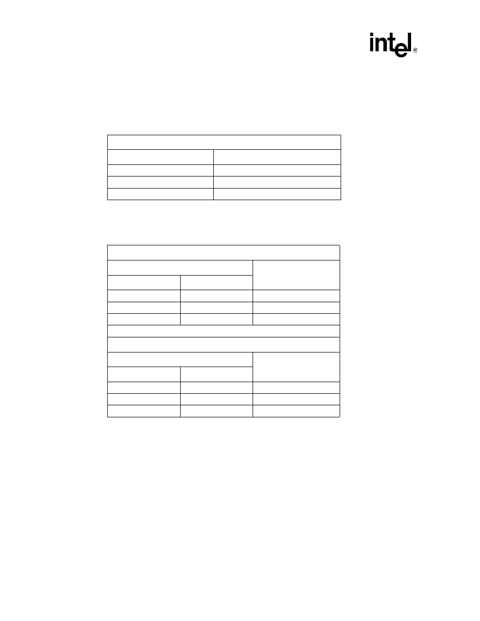
Table 31.
Network Link LEDs
For Channel A : L2 / For Channel B : L6
Link LED Status
Meaning
Off
No link
Solid Green
Link established
Blinking Green
Link with activity
NOTE:
Refer to
and
for LED (L2 and L6) placement on the
Front Panel.
Table 32.
Network Speed LEDs
For Ethernet controller Channel A : L3 & L4
Speed LED Status
Meaning
L3
L4
Solid Yellow
Off
1 Gbps connection
Off
Solid Green
100 Mbps connection
Off
Off
10 Mbps connection
For Ethernet controller Channel B : L7 & L8
Speed LED Status
Meaning
L7
L8
Solid Yellow
Off
1 Gbps connection
Off
Solid Green
100 Mbps connection
Off
Off
10 Mbps connection
NOTE:
Refer to
and
for LED (L3, L4, L7 and L8) placement
on the Front Panel.