2 rear panel – Mocomtech CRS-300 User Manual
Page 30
CRS-300 1:10 Redundancy Switch
Revision 16
Introduction
MN/CRS300.IOM
1–8
NOTE
1.4.2
Rear Panel
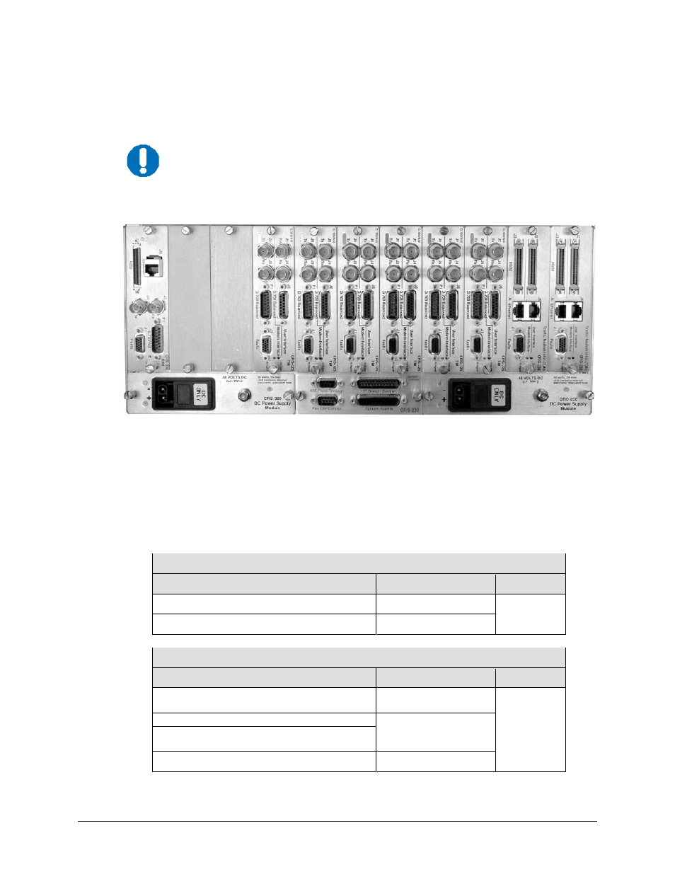
Figure 1-4 shows the back panel of the CRS-300 with a typically configured mix of TMI cards.
Because the RMI can have the capability for several TMIs, depending on user
requirements the CRS-300 may be able to use several different TMI cards
simultaneously.
Figure 1-4. CRS-300 Rear Panel – Configuration Example
1.4.3
Modem Interface Cards: CDM-570/570L, -600/600L, -625
The following tables indicate which TMI (Traffic Modem Interface) cards and which RMI
(Redundant Modem Interface) cards should be used with each modem and data type:
CDM-570/570L Modems
Data Type
TMI Type
RMI Type
G.703 T1/E1 Bal/Unbal
CRS-330 or CRS-340
CRS-310
EIA-422, V.35, EIA-232
CRS-340
CDM-600/600L Modems, CDM-625 Modem (in CDM-600 Emulator Mode)
Data Type
TMI Type
RMI Type
G.703 Bal (DDI, IDO, DDO, IDI)
Notes 1, 2
G.703 Unbal (DDI, IDO, DDO, IDI)
Notes 1, 2
CRS-330
CRS-310
EIA-422/V.35, EIA-232, LVDS
CRS-340
Note 3
G.703 Bal (DDI, IDO, DDO, IDI)
Notes 1, 2
G.703 Unbal
Notes 1, 2
Converts LVDS (Modem) to/from HSSI (User)
CRS-370
CRS-306
RMI
CRS-250
Power Supply Module
CRS-230
System Controller
(2X) Unused
Blanks
(6X) CRS-325
TMI
(2X) CRS-336
TMI
CRS-250
Power Supply Module