3 rmi card configuration reference – Mocomtech CRS-300 User Manual
Page 154
CRS-300 1:10 Redundancy Switch
Revision 16
Modem, RMI/TMI, and Switch Configuration MN/CRS300.IOM
5–10
5.3
RMI Card Configuration Reference
IMPORTANT
The RMI Card Configuration Reference is provided for RMI identification
purposes only. All RMI cards are shipped pre-configured and do not require
adjustments by the user.
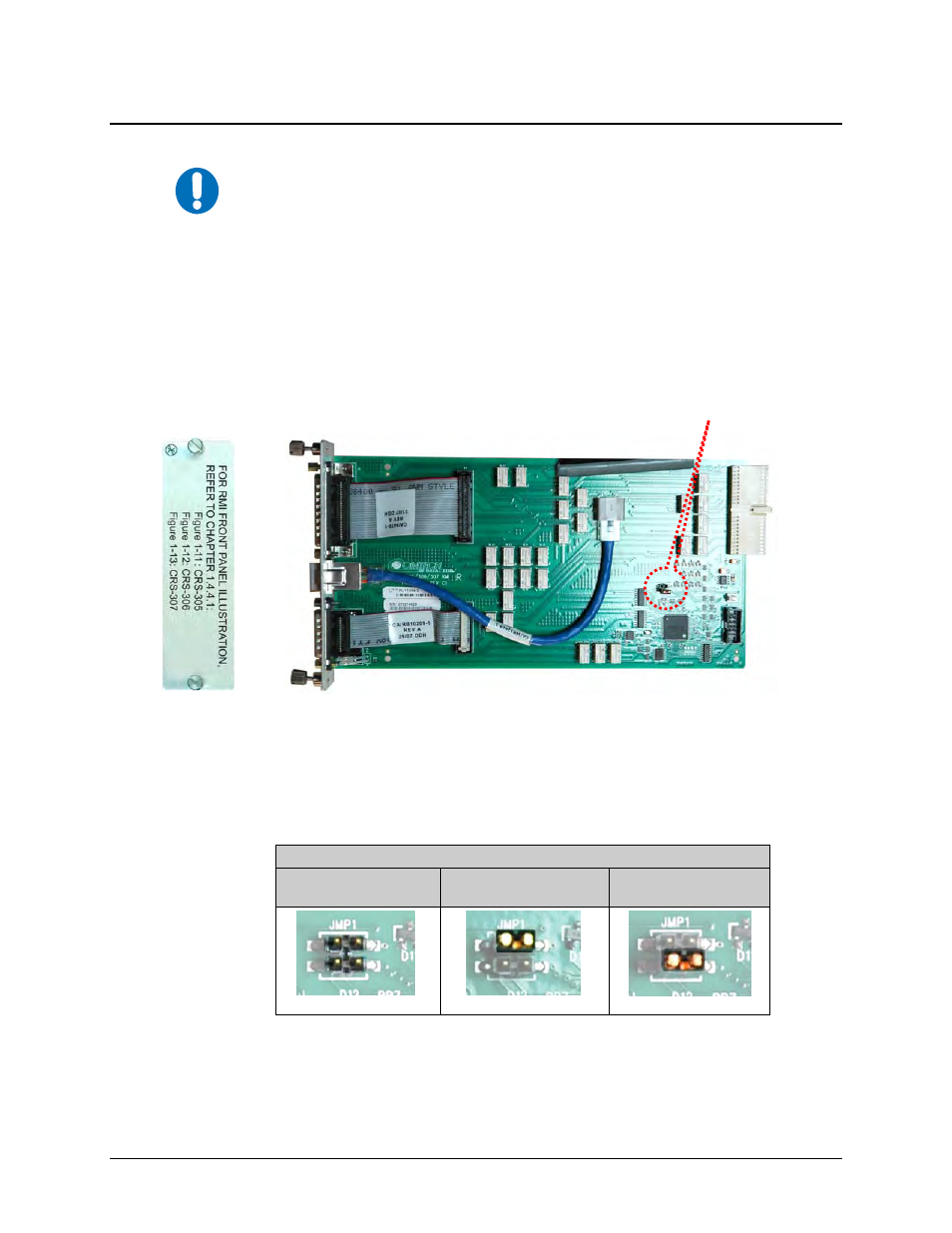
The CRS-305, CRS-306, and CRS-307 RMI cards come pre-configured for proper operation. All
three cards share a common printed circuit board (CEFD P/N PC/11494x); what distinguishes the
cards from one another is the configuration of front panel connectors, and configuration of the
JMP1 jumper setting on the PCB.
shows the PCB used for all three RMIs, with the typical JMP1 jumper location
identified.
Figure 5-3. CEFD P/N PC/11494x RMI PCB
(CRS-307 shown)
illustrates the JMP1 jumper settings, as established at the factory for each RMI card.
Table 5-1. RMI JMP1 Factory-configured Jumper Settings
‘JMP1’ Jumper Setting – AS SHIPPED
CRS-305
(No jumpers)
CRS-306
(Pins 1 to 2 jumped)
CRS-307
(Pins 3 to 4 jumped)
Jumper JMP1
Front
view
Side
view