Mocomtech CRS-300 User Manual
Page 176
CRS-300 1:10 Redundancy Switch
Revision 16
Connector Pinouts
MN/CRS300.IOM
6–8
6.2.6
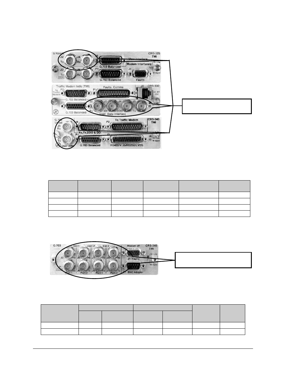
Unbalanced G.703 – BNC Connectors (CRS-325/330/340)
Table 6-9 indicates the TMI User Data Interface BNC connectors (Unbalanced G.703) on the
CRS-325, CRS-330 and CRS-340.
Table 6-9. Unbalanced G.703 Connectors
BNC
Connector
TMI CRS-325
Ref Des
TMI CRS-330
Ref Des
TMI CRS-340
Ref Des
Description
Direction
Rx-IDO J4
J2
J3 Rx,
G.703 Out
Tx-IDI J2
J5
J4 Tx,
G.703 In
IDI
—
J3
—
Insert data input
In
DDO
—
J4
—
Drop data output
Out
6.2.7
Unbalanced G.703 – 4-Port BNC Connectors (CRS-345)
Table 6-10 indicates the TMI User Data Interface multiport BNC connectors (Unbalanced G.703)
on the CRS-345.
Table 6-10. Unbalanced G.703 Connectors
BNC Connector
Slot 1
Slot 2
Description
Direction
Port 1
Ref Des
Port 2
Ref Des
Port 1
Ref Des
Port 2
Ref Des
Rx J3
J5 J7 J9
Rx,
G.703
Out
Tx J4
J6 J8
J10
Tx,
G.703
In
TMI User Data Interface:
Unbalanced G.703 connectors
TMI User Data Interface:
Unbalanced G.703 connectors