4 hssi interface via the crs370 tmi, 4 hssi interface via the crs-370 tmi – Mocomtech CRS-300 User Manual
Page 161
CRS-300 1:10 Redundancy Switch
Revision 16
Modem, RMI/TMI, and Switch Configuration MN/CRS300.IOM
5–17
5.4.4
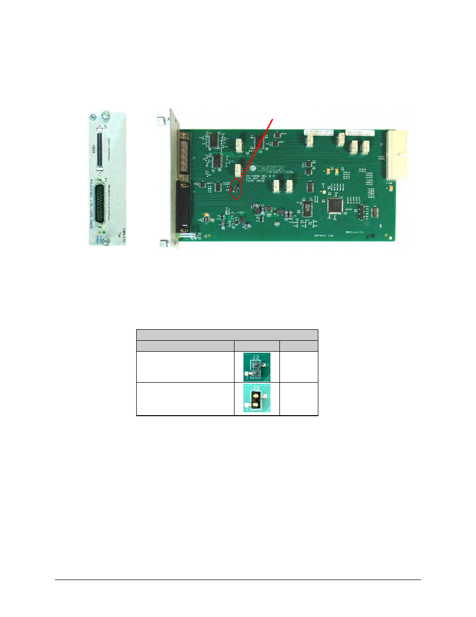
HSSI Interface via the CRS-370 TMI
Jumper J2 on CRS-370 TMI Card selects the functionality of the control signals CA and TA.
Figure 5-10
shows this TMI as shipped from the factory, with the J2 jumper open.
Figure 5-10. CRS-370 HSSI to LVDS TMI Card
(Jumper shown open)
illustrates the control signal configuration J2 jumper settings available on the CRS-370
TMI.
Table 5-8. CRS-370 Jumper Settings
Jumper ‘J2’
Control Signal Setting
Jumpers
Settings
TA to CA Loop
(TMI as-shipped)
None
• TA controls TX carrier
• RR controls CA
Installed
Front view
Side View
Jumper J2