Mocomtech CRS-300 User Manual
Page 157
CRS-300 1:10 Redundancy Switch
Revision 16
Modem, RMI/TMI, and Switch Configuration MN/CRS300.IOM
5–13
5.4.2
EIA-232/-422, V.35 Interfaces via the CRS-320 and CRS-340 TMIs
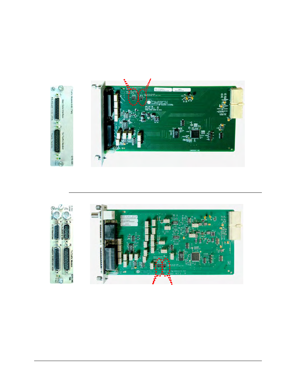
Jumpers JP1 and JP2 on the CRS-320 (obsolete) and CRS-340 TMI cards set the functionality of
the control signals DTR/DSR and RTS/CTS. Figure 5-6 and Figure 5-7 show these TMIs as
shipped from the factory, with the JP1 and JP2 jumper settings open.
Figure 5-6. CRS-320 EIA-232/EIA-422 TMI Card
(Jumpers shown open)
Figure 5-7. CRS-340 EIA-232/-422/G.703 TMI Card
(Jumpers shown open)
Jumper JP2
Jumper JP1
Front
view
Side
view
Jumper JP2
Jumper JP1
Front view
Side view