beautypg.com
CRS-300 1:10 Redundancy Switch
Revision 16
Cables and Connections
MN/CRS300.IOM
4–62
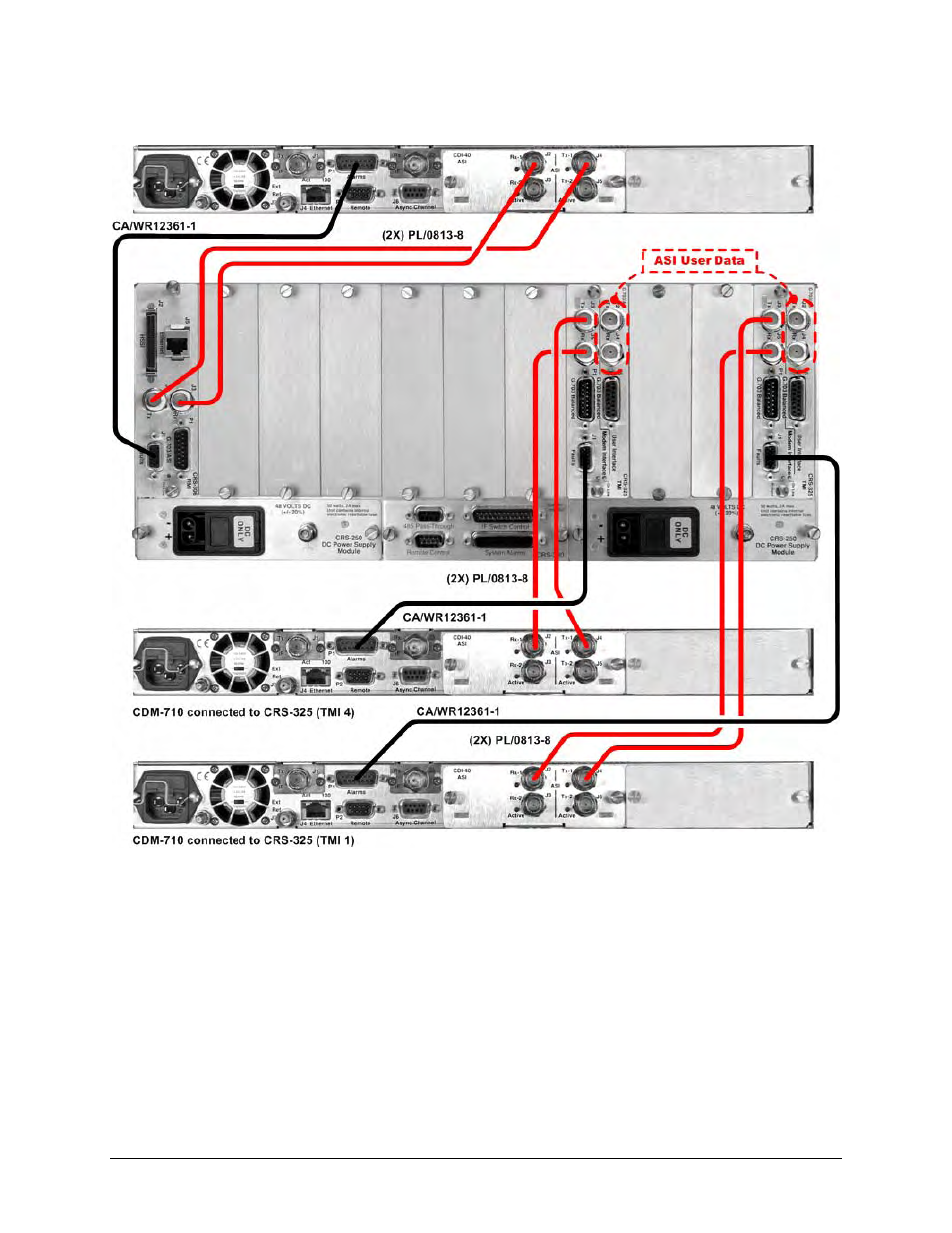
Figure 4-28. Control and Data Cables Example #1 – CRS-300 to CDM-710
(Connections shown for RMI & TMIs 1 and 3 only)