Mocomtech CRS-300 User Manual
Page 156
CRS-300 1:10 Redundancy Switch
Revision 16
Modem, RMI/TMI, and Switch Configuration MN/CRS300.IOM
5–12
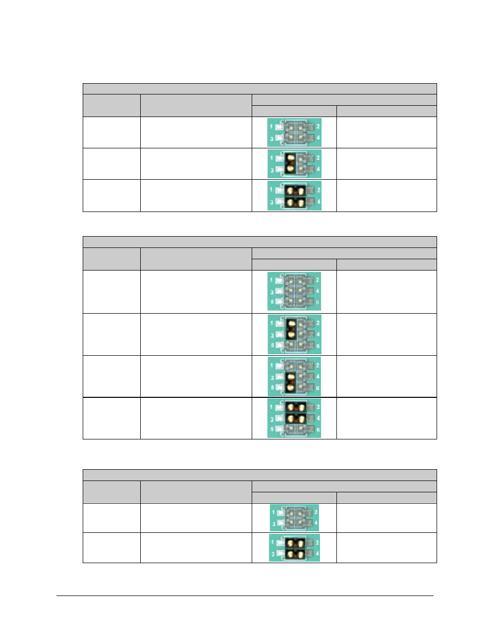
Table 5-2. CRS-316 Jumper ‘JP1’ Settings
User Interface Jumper ‘JP1’
Modem
Control Signal Setting
Jumper Settings
Detail
Pin Settings
CDM-625
CS_B & RS_B Signals
Not Connected
N/A
(Note: TMI as shipped)
CDM-625
CS_B to RS_B
Loop Connected
at User DB-25 Connector
Pin 1 to Pin 3
SLM-5650A
CS_B & RS_B
Routed to online modem
Pin 1 to Pin 2;
Pin 3 to Pin 4
Table 5-3. CRS-316 Jumper ‘JP2’ Settings
User Interface Jumper ‘JP2’
Modem
Control Signal Setting
Jumper Settings
Detail
Pin Settings
CDM-625
CS_A/CTS & RS_A/RTS
Not Connected
N/A
(Note: TMI as shipped)
CDM-625
CS_A/CTS & RS_A/RTS
Loop Connected
at User DB-25 Connector
Pin 1 to Pin 3
CDM-625
RTS
Controls online modem’s Tx
IF mute operation
Pin 3 to Pin 5
SLM-5650A
CS_A/CTS & RS_A/RTS
Routed to online modem
Pin 1 to Pin 2;
Pin 3 to Pin 4
Table 5-4. CRS-316 Jumper ‘JP3’ through – ‘JP6’ Settings
User Interface Jumpers ‘JP3’ through ‘JP6’
Modem
Control Signal Setting
Jumper Settings
Detail
Pin Settings
CDM-625
DM/DSR, CS , RS, CS/CTS,
RS/RTS, DM/DSR
Not Connected
N/A
(Note: TMI as shipped)
SLM-5650A
DM/DSR, CS , RS, CS/CTS,
RS/RTS, DM/DSR
Routed to Traffic modem
Pin 1 to Pin 2;
Pin 3 to Pin 4