A.4.13 g.703 data cable for cdm-700 – Mocomtech CRS-300 User Manual
Page 231
CRS-300 1:10 Redundancy Switch
Revision 16
Cable Drawings
MN/CRS300.IOM
A-29
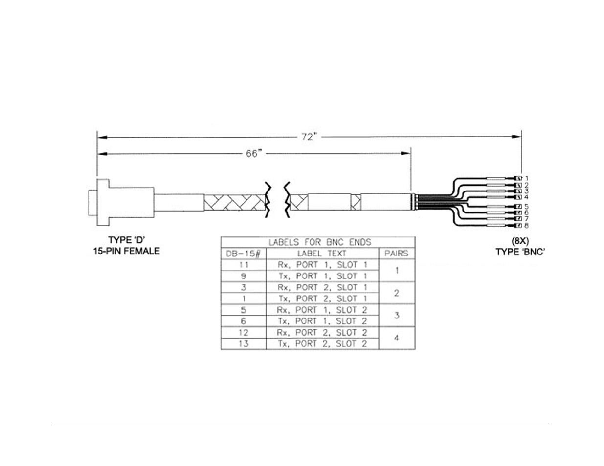
A.4.13 G.703 Data Cable for CDM-700
Figure A-25 shows the cable used to connect the CRS-306 Switch RMI to the Redundant CDM-700 G.703 Interface cards. Depending on
the modem configuration, a modified version of this cable that employs only four of the eight BNC connectors is used. See
Chapter 4.7
CDM-700 Modem Connections
for illustrations of this alternate use.
Figure A-25. CDM-700 G.703 Data Cable (CA/RF12279-1)