Component relationship diagram – Grizzly G0509 User Manual
Page 57
G0509 & G0509G 16" x 40" Lathe
-55-
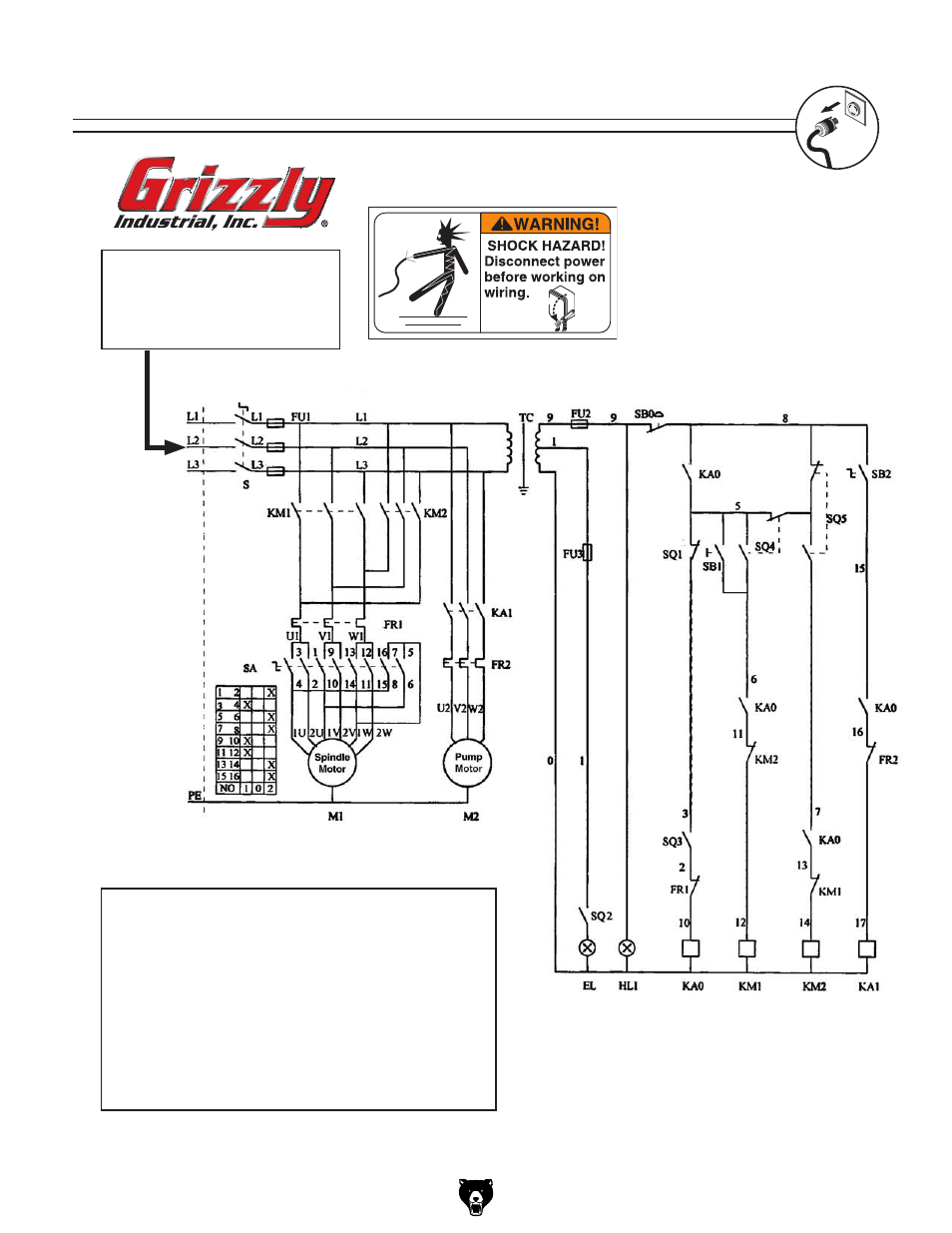
component relationship diagram
if a phase converter is being
used, connect the “Wild Wire”
or “manufactured leg” to l2 or
contactor and transformer failure
may result!
OFF
sB2: pump switch
tC: transformer
s: Motor speed switch
El: Work lamp
hl1: power lamp
M1: spindle Motor
M2: pump Motor
Fu2: Fuse
Fu3: Fuse
sB1: Jog Button
sQ1: Brake switch
sQ2: Work lamp switch
sQ3: Belt Cover limit switch
sQ4: spindle Motor switch
sQ5: spindle Motor switch
sB0: Emergency stop Button
KM1: spindle Motor Contactor
KM2: spindle Motor Contactor
Fr1: spindle Motor thermal relay
KA1: pump Contactor
KA0: Master power Contactor
Fr2: pump Motor thermal relay
Fu1: Main Circuit Breaker
see
figures
74 through 85 component locations, and
pages 56 and 57 for wire connections.