Feed rod and leadscrew gearbox ratio levers, Notice – Grizzly G0509 User Manual
Page 30
-28-
G0509 & G0509G 16" x 40" Lathe
feed rod and
leadscrew
gearbox ratio
levers
the leadscrew/feed rod lever (
figure 21) engag-
es and disengages the leadscrew and feed rod
simultaneously. When the lever is moved up or
down, the rotation of the leadscrew and feed rods
are simultaneously reversed.
the three-position gearbox high/low range lever
(
figure 21) will put the gearbox into high range
"
h", low range "l", or neutral "
I".
note: Make sure to loosen the carriage lock
(
Figure 28) when apron power feed or threading
are to be used. The carriage lock is used only to
increase carriage stability when facing operations
are in process.
NOTICE
only shift the gearbox levers when spindle
speed is less than 500 rpm and the gear-
box speed range lever is in neutral. never
force a lever. if the lever will not engage, use
the jog button when applicable so the teeth
mesh and the lever drops into position.
figure 21. gearbox input and output controls.
leadscrew/Feed
rod direction lever
(output)
gearbox
high/low
range
lever
(input)
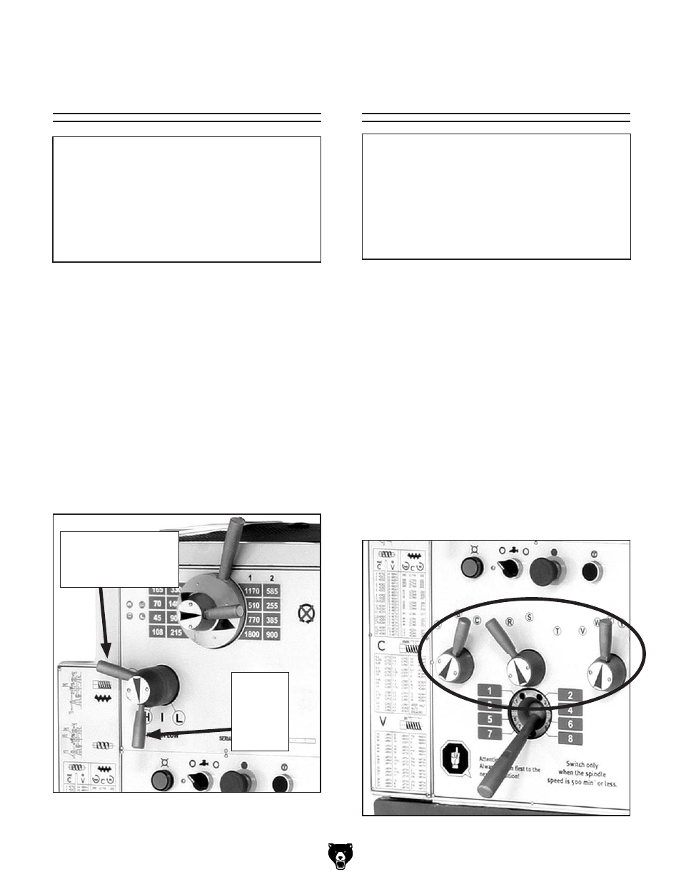
figure 22. gearbox range levers.
NOTICE
only shift the gearbox levers when spindle
speed is less than 500 rpm and the gear-
box speed range lever is in neutral. never
force a lever. if the lever will not engage, use
the jog button when applicable so the teeth
mesh and the lever drops into position.
the gearbox has a series of levers used for con-
trolling the feed rod and leadscrew feed rates in
relationship with the spindle speed.
Based on the threading and feed rate chart, you
can shift the gearbox to accommodate an elabo-
rate array of feed rates. the three gearbox range
levers (
figure 22) have multiple lettered posi-
tions (
figure 24), and when moved according
to the threading chart and example on the next
page, you can quickly change the feed rate. the
example on the next page shows the lathe setup
to cut a
"3.5mm" thread using the "lcr8y" lever
combination.
note: The change gear must be in the position
shown in
Figure 23.