Grizzly G0509 User Manual
Page 52
-50-
G0509 & G0509G 16" x 40" Lathe
11. place the chuck key in the cam-lock socket
and keep the spindle from rotating.
12. using a spanner wrench, or hammer-and-
punch, loosen the preload spanner nut
(
figure 70) counterclockwise 1 turn.
13. place a wooden block over the outboard end
of the spindle, hit the block soundly with a
metal or heavy dead blow hammer (
figure
71). your goal is to slide the spindle forward
just enough to introduce spindle end-play that
you can feel by hand.
8. Move the carriage an additional 0.100" toward
the headstock.
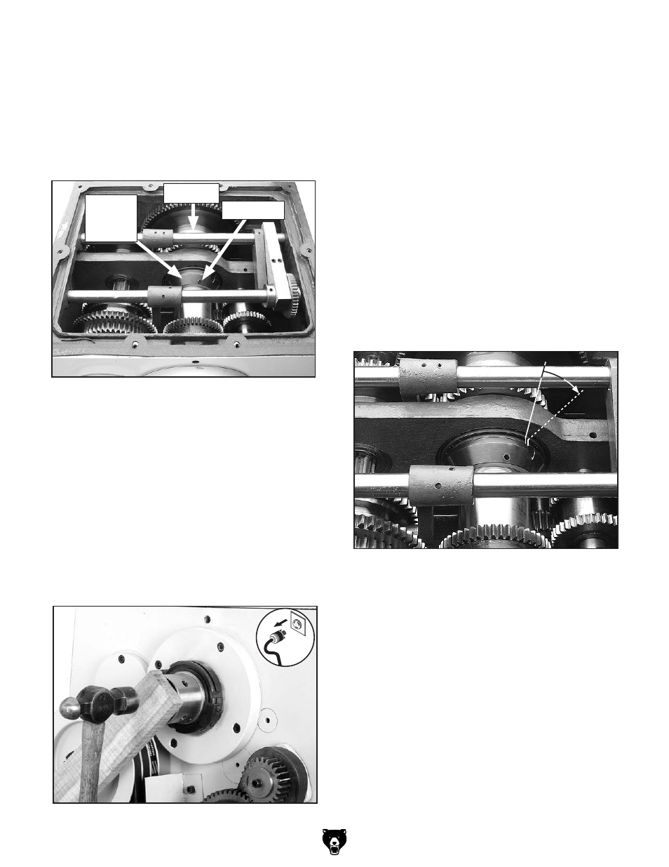
9. using a 5mm hex wrench, remove the head-
stock lid to expose the headstock gears.
10. remove the preload spanner nut set screws
(
figure 70) with a 3mm hex wrench.
figure 70. preload spanner nut.
figure 71. introducing detectable end-play.
set screw
preload
spanner
nut
since it can take great effort to turn the pre-
load spanner nut, you may find it difficult to
know if you have gone past the zero end-
play point or not. you may find it easiest to
have someone watch the dial for you while
you tighten the inner spanner nut. if you think
you may have gone past the zero end-play
point, take the time to unload the bearings
as described earlier, then re-tighten the inner
spanner nut until you know you have reached
the correct setting.
When you are confident that you have adjust-
ed the preload spanner nut until zero spindle
end-play and but preload exists, you now
must move the spanner nut inward and addi-
tional 0.001" to set the preload.
14. to set the preload, rotate the spanner nut an
additional 0.16" as shown in
figure 72.
figure 72. preload spanner nut adjustment.
0.16"
15. reinstall the setscrews in the preload span-
ner nut.
16. position the gasket correctly, and re-install
the headstock cover.
17. tighten the outboard spindle spanner nut
until it is snug and reinstall the locking set-
screw.
18. reinstall the lathe end cover, and make sure
the counterweights (
figure 73) do not rub on
the cover when the lathe is turned on.
spindle