Power feed direction knob, Tool post & holder, Manual feed handwheels – Grizzly G0509 User Manual
Page 32
-30-
G0509 & G0509G 16" x 40" Lathe
power feed
direction Knob
your lathe can cut left or right while feeding or in
and out when facing. the feed direction is con-
trolled by the feed direction knob shown in
figure
26.
figure 26. Feed direction knob.
power Feed direction Knob
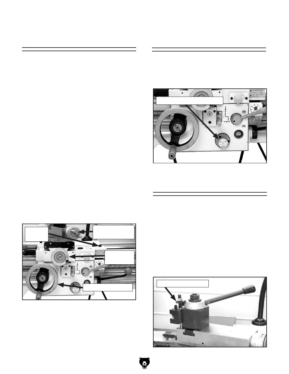
tool post & holder
Cutting tools can be secured and removed by
tightening or loosening the clamping screws in
the top of the tool holder (
figure 27). A threaded
stud is mounted in the top of the holder and has
a knurled thumb wheel. rotating the thumb wheel
raises or lowers the tool holder so the cutting tool
can be indexed on the workpiece. the handle on
the tool post is rotated to lock and unlock the tool
holder, which rests in the dovetail ways. the tool
post may be rotated by loosening the nut at the
top of the tool post.
figure 27. Quick change tool post.
manual feed
handwheels
carriage handwheel
the carriage handwheel (
figure 25) moves the
carriage left or right along the bed. remember
the carriage lock must be loosened to allow for
carriage movement during manual and power fed
operations.
compound slide handwheel
the compound slide handwheel can adjust the
cross slide at any angle. Angle adjustment is
locked by two cap screws on the base of the
top slide. the graduated dial can be rotated to
read metric or inch conventions by turning it 180°
degrees by holding the handwheel with one hand
and turning the dial hub with the other.
cross slide handwheel
the cross slide handwheel moves the cross slide
toward and away from the work. turning the dial
clockwise moves the slide toward the workpiece.
the graduated dial can be rotated to read metric
or inch conventions by turning it 180° degrees by
holding the handwheel with one hand and turning
the dial hub with the other.
figure 25. handwheel locations.
Cross slide
handwheel
Compound slide
handwheel
Carriage handwheel
Carriage
lock
Knurled thumbwheel