V-belts, Brake & switch – Grizzly G0509 User Manual
Page 50
-48-
G0509 & G0509G 16" x 40" Lathe
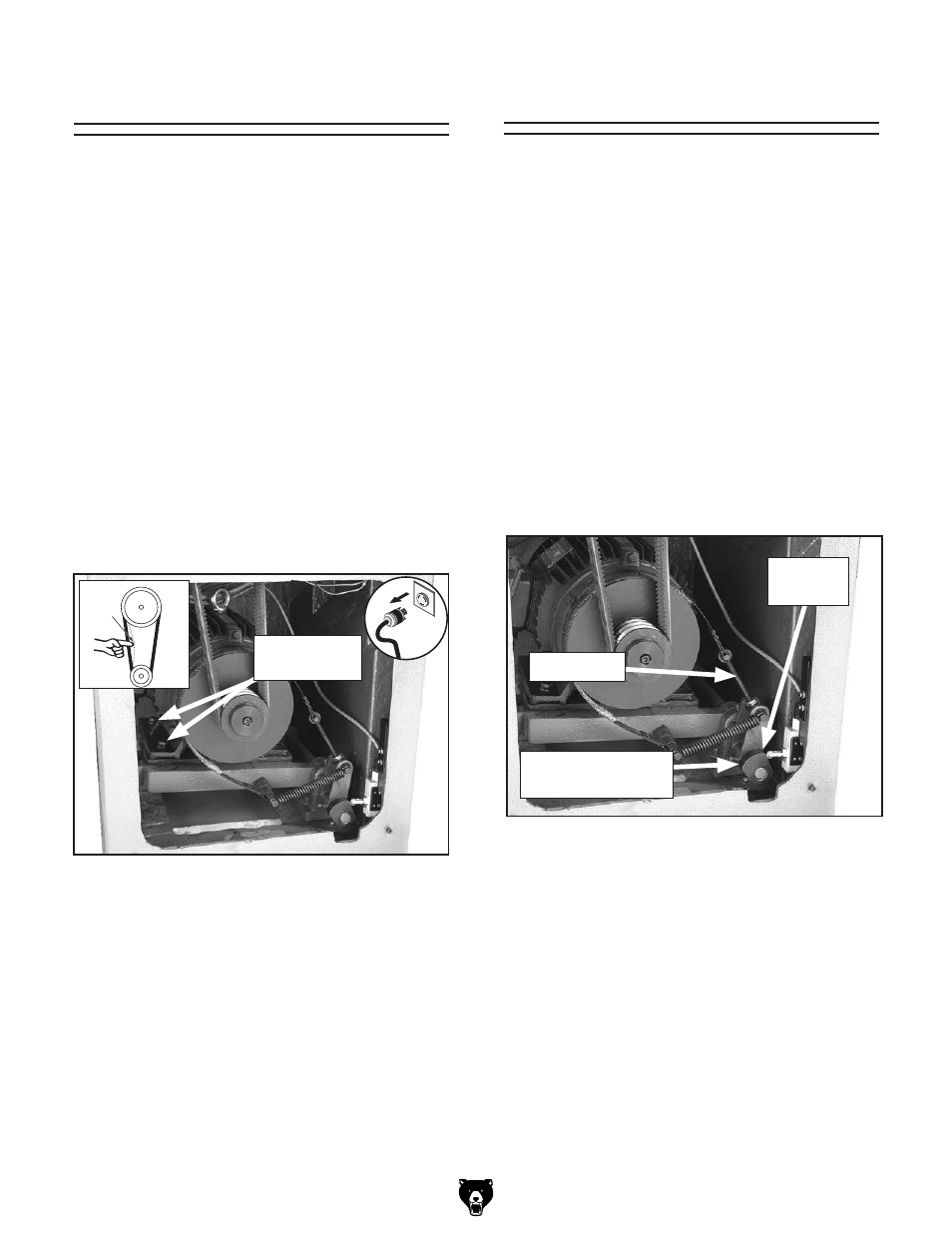
v-belts
to adjust or replace the v-belts on the lathe:
1. disConnECt lAthE FroM poWEr!
2. open the lathe base end cover (figure 64).
3. using a wrench, adjust the belt tension hex
nuts (see
figure 64) until there is approxi-
mately
1
⁄
2
" belt deflection on each belt when
pressed firmly in the center between the pul-
leys.
note: Replace all three belts as a matched
set even if one shows cracking, glazing, or
fraying.
4. reinstall the rear cover.
brake & switch
to adjust the brake and brake switch:
1. disConnECt lAthE FroM poWEr!
2. open the lathe base end cover (figure 64).
3. using a wrench, adjust the brake rod (figure
65) so, when the foot pedal is pressed, the
brake band firmly clamps the drum. When
released, the brake band should be loose on
the drum.
note: Replace the brake band when the fric-
tion material is worn down to approximately
2mm thick.
4. Adjust the brake switch cam so when in the
released position, there is 1 to 2mm gap
between the cam and the brake switch push-
rod roller (
figure 65).
5. reinstall the safety cover and test foot brake
operation.
figure 65. Brake band and switch.
Brake rod
1-2 mm
gap
Brake switch Cam
and Cap screw
After consistent lathe usage, it will be necessary
to compensate for brake lining wear.
during the life of the lathe, it will be necessary to
compensate for belt wear.
figure 64. V-belt adjustment.
Belt tension
Adjustment
Pulley
Deflection
Pulley