FUJITSU M304X User Manual
Page 66
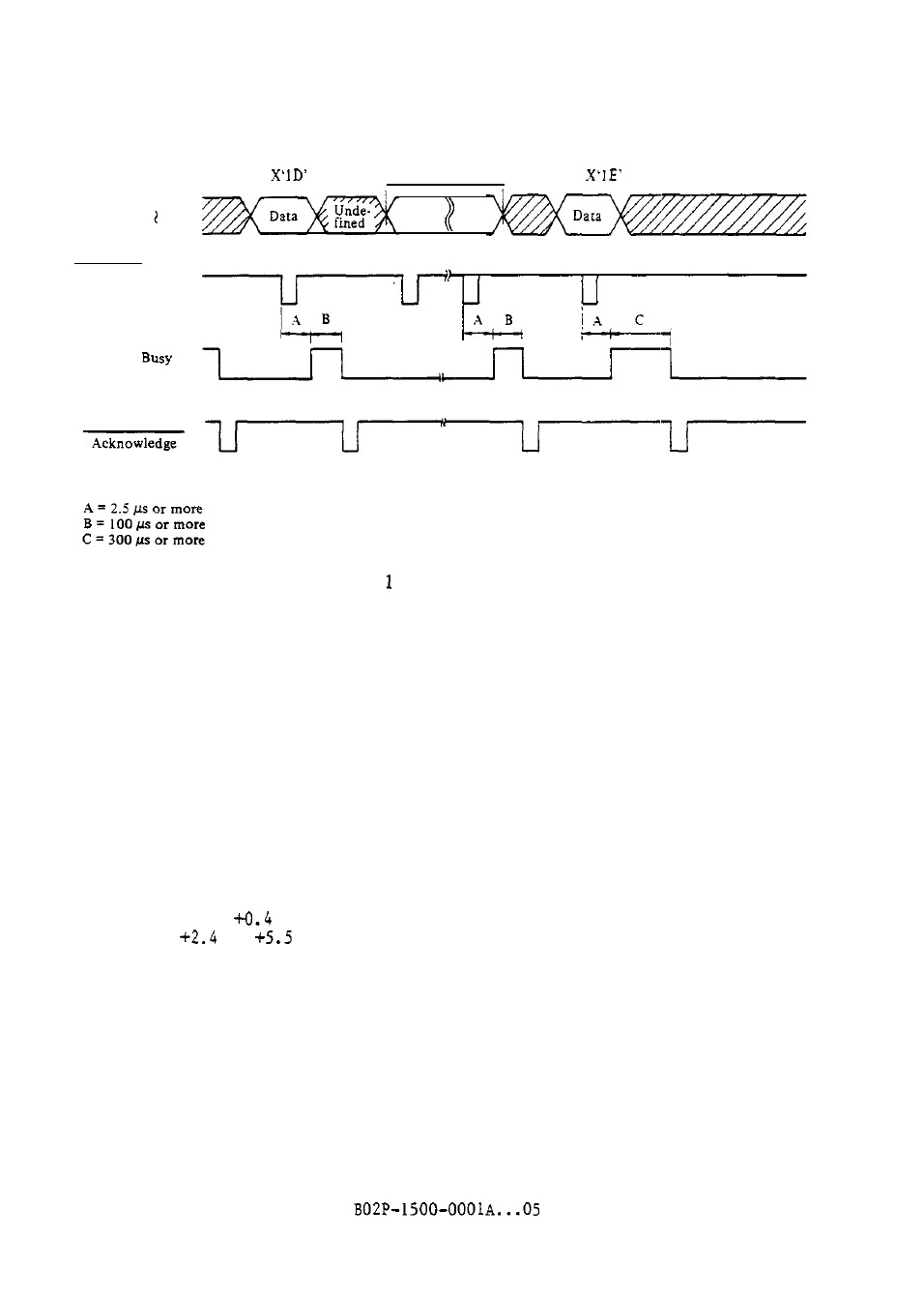
Start code
VFU data
Stop code
I
I
Data Bit I
Data Bit 8
Data Strobe
Note:
The Busy signal is st to ech time an FCB data byte is received
during a sequence between the start and stop codes.
Figure 5.7 FCB data receive timing chart
5.2.2 Physical specifications of interface signals
The physical specifications of Centronics-interface signals consist of
electrical specifications, interface cable specifications, and connector pin
assignment specifications.
(1) Electrical specifications
Signal levels must be within the following ranges:
Low 0.0 to
v
High
to
V
Note:
The signal level above are at the interface connector.
Incorrect signals may be issued at power-on and power-off.
The interface signal driver and receiver must be the same as those shown
in Figure 5.8.
5 - 8
- FTP-633GA1021 (6 pages)
- KA02038-Y820 (1 page)
- FTP-632MCL102 (7 pages)
- FTP-621MCL102 (6 pages)
- FTP-604 FTP-644MCL002 (7 pages)
- FTP-629MCL103-R (7 pages)
- FTP-641MCL351 (6 pages)
- C145-C037-01EN (123 pages)
- FTP-030P (3 pages)
- FTP-627USL401 (9 pages)
- FTP-621CT001 (6 pages)
- FTP-629MCL054 (7 pages)
- FTP-634MCL001 (7 pages)
- FTP-624MCL002 (8 pages)
- Printer (4 pages)
- FTP-040HF Holder Series (2 pages)
- P3PC-1442-01EN (17 pages)
- FTP-631MCL201 (6 pages)
- FTP-628WSL120 (7 pages)
- ScandAll PRO P2WW-2410-01ENZ0 (45 pages)
- DL6400Pro (247 pages)
- FTP-632MCL003 (7 pages)
- FTP-633MCL400 (12 pages)
- FTP-631MCL302 (6 pages)
- 102 (8 pages)
- FTP-622MCL302 (6 pages)
- FTP-642MCL302 (7 pages)
- 16DV (39 pages)
- FTP-639MCL103/383-R (7 pages)
- FTP-637MCL401 (6 pages)
- DL9400 (250 pages)
- FTP-631MCL352 (6 pages)
- FTP-631MCL101 (6 pages)
- FTP-639MCL353 (7 pages)
- FTP-641MCL302 (6 pages)
- FTP-622DCL001/011 (8 pages)
- FTP-628MCL401 (9 pages)
- FTP-621MCL201 (6 pages)
- FTP-641MCL101/102 (6 pages)
- FTP-632MCL301 (6 pages)
- DL3800 (262 pages)
- DL6400 (247 pages)
- FTP-627USL631 (10 pages)
- FTP-624MCL304 (7 pages)