FUJITSU M304X User Manual
Page 28
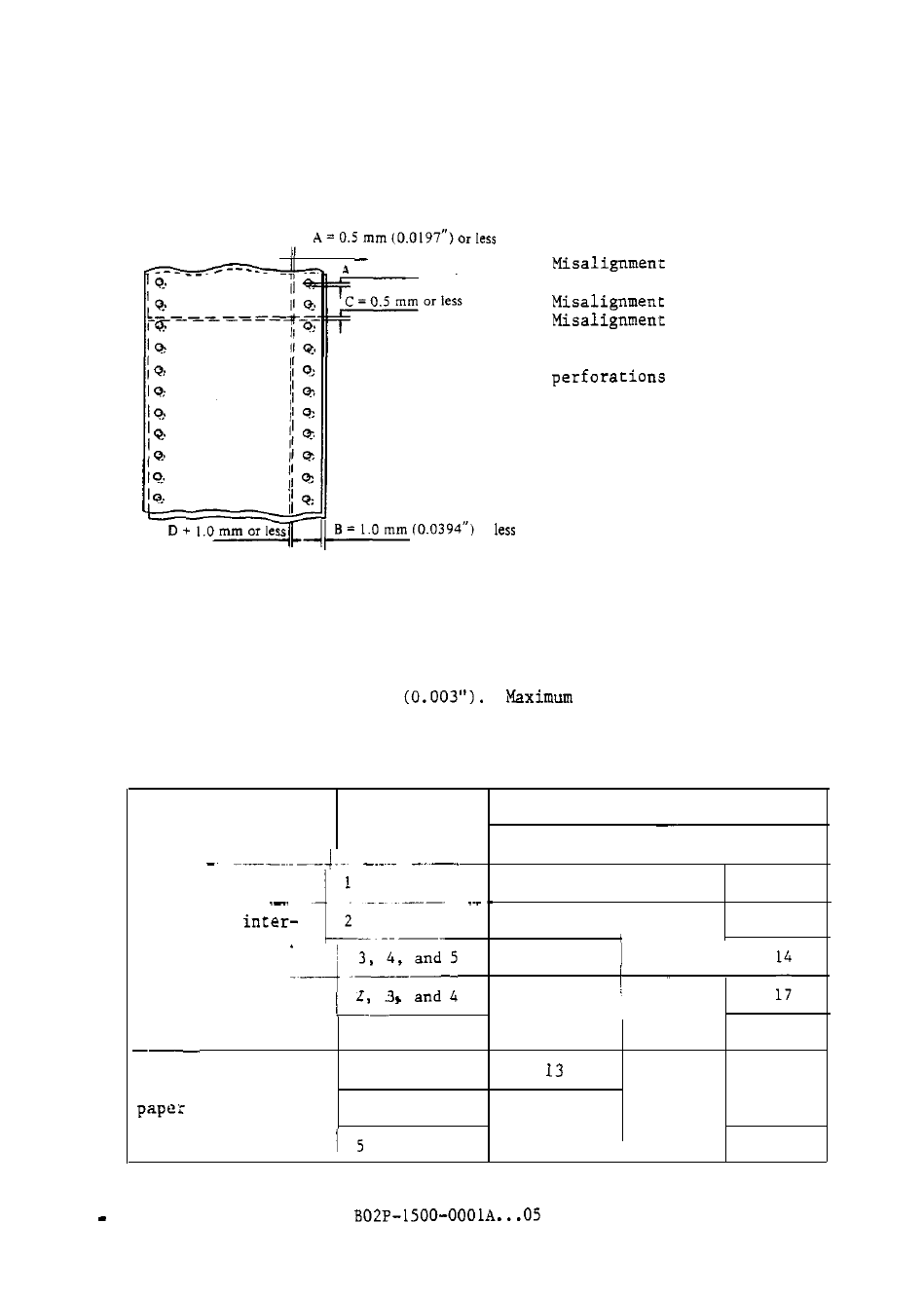
(2) Misalignment of paper
Misalignment between layers should be within the range shown in Figure
2.15.
= 0.5 mm or less
or
A:
B:
c:
D:
of pin feed
holes
of edges
of horizontal
perforations
Misalignment of vertical
Figure 2.15 Allowable incorrect alignment of multiple-part forms
(3) Thickness of parts
Thickness of parts should be uniform.
Thickness deviation in the print
area must be within 0.076 mm
total thickness of forms
(including edges) is 0.6 mm (0.0236").
Table 2.8 indicates recommended
bond weight of each layer according to forms type.
Table 2.8 Recommended bond weight of forms
Bond weight (pound/bond)
Forms type
No. of parts
Recommended Minimum Maximum
Single-part forms
1
17
1 5
2 8
Forms with
2
14
17
leaved carbon paper
12.5
125
Carbon-backed forms
11
I 11
5
11
Forms using
2 and 3
17
carbonless copy
4
11
11
11
2 16
- FTP-633GA1021 (6 pages)
- KA02038-Y820 (1 page)
- FTP-632MCL102 (7 pages)
- FTP-621MCL102 (6 pages)
- FTP-604 FTP-644MCL002 (7 pages)
- FTP-629MCL103-R (7 pages)
- FTP-641MCL351 (6 pages)
- C145-C037-01EN (123 pages)
- FTP-030P (3 pages)
- FTP-627USL401 (9 pages)
- FTP-621CT001 (6 pages)
- FTP-629MCL054 (7 pages)
- FTP-634MCL001 (7 pages)
- FTP-624MCL002 (8 pages)
- Printer (4 pages)
- FTP-040HF Holder Series (2 pages)
- P3PC-1442-01EN (17 pages)
- FTP-631MCL201 (6 pages)
- FTP-628WSL120 (7 pages)
- ScandAll PRO P2WW-2410-01ENZ0 (45 pages)
- DL6400Pro (247 pages)
- FTP-632MCL003 (7 pages)
- FTP-633MCL400 (12 pages)
- FTP-631MCL302 (6 pages)
- 102 (8 pages)
- FTP-622MCL302 (6 pages)
- FTP-642MCL302 (7 pages)
- 16DV (39 pages)
- FTP-639MCL103/383-R (7 pages)
- FTP-637MCL401 (6 pages)
- DL9400 (250 pages)
- FTP-631MCL352 (6 pages)
- FTP-631MCL101 (6 pages)
- FTP-639MCL353 (7 pages)
- FTP-641MCL302 (6 pages)
- FTP-622DCL001/011 (8 pages)
- FTP-628MCL401 (9 pages)
- FTP-621MCL201 (6 pages)
- FTP-641MCL101/102 (6 pages)
- FTP-632MCL301 (6 pages)
- DL3800 (262 pages)
- DL6400 (247 pages)
- FTP-627USL631 (10 pages)
- FTP-624MCL304 (7 pages)