FUJITSU M304X User Manual
Page 25
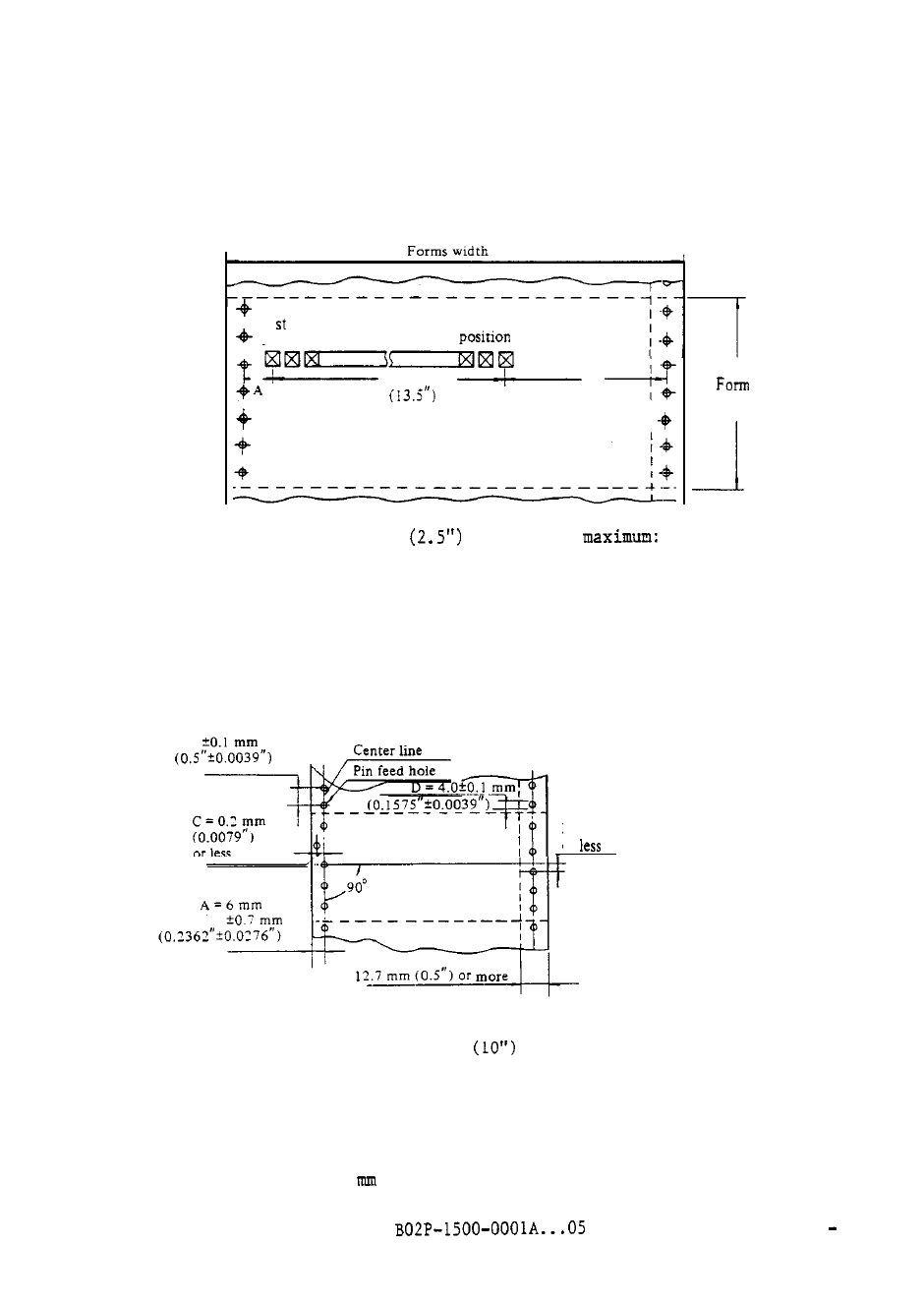
(2) Positions and dimensions of the printing area
Figure 2.11 illustrates the distances between the leftmost and rightmost
print-position centers of the printing area and the pin feed hole center.
I print
position
136th print
342.9 mm
B
length
A- maximum: 63.5 mm
B-
68.6 mm (2.7")
Figure 2.11 Leftmost and rightmost print positions
(3) Pin feed holes
Pin feed holes must be round.
The dimensions relating to pin feed holes
are given in Figure 2.12.
B = 12.7 mm
E = 0.2 mm
or
A: Distance between
the forms edge and
pin feed holes.
B: Distance between
two consecutive pin
feed holes.
C
: Misalignment of the
pin-feed hole
center with other
holes.
D: Diameter of a pin
feed hole.
E: Misalignment of the
pin feed hole with
a hole on the
opposite side.
Note:
The total misalignment of any two holes on opposite sides of
forms along a 254 mm
length must not exceed 0.3 mm
(0.0118").
Figure 2.12 Dimensions relating to pin feed holes
Poorly shapted pin feed holes and misalignment between left and right pin
feed holes may result in inferior paper tensile strength. Misalignment
must be within 0.2
(0.0079").
2 13