FUJITSU M304X User Manual
Page 61
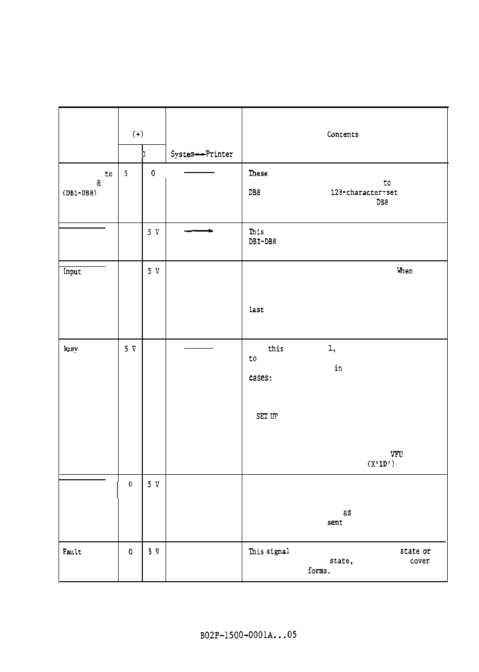
Table 5.1 Centronics-compatible interface signal lines
Signal
level
Signal name
Direction
1
Data Bit 1
V
signals are data (character code, FCB data,
Data Bit
control code) input from the lost
the printer.
is used when the
print band
is used.
(For ASCII
'i-bit codes,
can be
ignored.)
Data Strobe
0
signal is a synchronizing clock for reading
input to the printer. The data is read
at the rising edge of this signal.
Prime
0
This signal initializes the printer.
it
receives this signal, the printer clears the FCB,
PDB, and control functions and goes offline.
After clear, TOF is the first line and BOF is the
line.
When this signal is received during
printing or forms feed, the settings are cleared
after the operation.
0
When
signal is
the printer is not ready
receive data.
This signal is issued
one of the following
. During printing
. During forms feed
. During offline state (including the TEST and
modes)
. When the printer is inoperable (fault state)
When the printer responds to a control code
(except the DC1 code)
. When the printer responds to each
data byte
following to the start: code
Acknowledge
This signal is sent to the mainframe when the
printer can receive data. This signal is used to
inhibit sending signal by the host until the
printer operation such
loading
the
received
code. This signal is
with a 2.5 to 5.5 us
width pulse.
is issued during an error
another or inoperable
such as top
open or end of
(Fault state)
5
- 3