MOTU 828x 28x30 Audio Interface with ThunderTechnology User Manual
Page 79
C U E M I X F X
79
Stereo settings
Inputs that have been grouped as stereo pairs in the
Inputs tab (Figure 9-3) provide two stereo modes
(Figure 9-8):
Normal
and
M/S
. M/S mode provides
decoding for a mid-side microphone configu-
ration.
The
Width
knob (Figure 9-8) provides control over
the stereo imaging, going from a full stereo image
to mono (both channels panned equally). See
“Width” on page 73.
The
Swap L/R
button (Figure 9-8) lets you switch
the left and right channels.
Overload protection (mic/guitar inputs only)
The Overload Protection section (Figure 9-8)
provides two features that help prevent digital
clipping on the two front-panel mic/guitar inputs.
These options are only available on these two
preamp-equipped inputs.
V-Limit™
(Figure 9-8) is a hardware limiter that
helps prevent digital clipping from overloaded
input signals. With V-Limit engaged, signals can go
above zero dB (with limiting applied) to as high as
+12 dB above zero with no distortion due to digital
clipping. Click the
Lookahead
option for even
better protection against sharp transients.
Additional or alternative protection can be applied
to the mic/guitar inputs by enabling
Soft Clip
(Figure 9-8). When enabled, Soft Clip engages just
before clipping occurs and helps further reduce
perceptible distortion.
Talkback section
Click the
Talkback
or
Listenback
button
(Figure 9-8) to toggle whether the input is the
Talkback or Listenback input. Only one input can
be the talkback input, and only one input can be
the listenback input. See “Talkback and listenback”
on page 92.
Reverb section
The
Send
in the reverb section (Figure 9-8) is the
same control as the reverb send in the Input tab
channel strip (Figure 9-3). See “Reverb send” on
page 76. If the input is currently not grouped as a
stereo pair in the Input tab (it is operating as a
mono input), use the reverb
Pan
knob (Figure 9-8)
to pan the mono signal for the stereo reverb
processor.
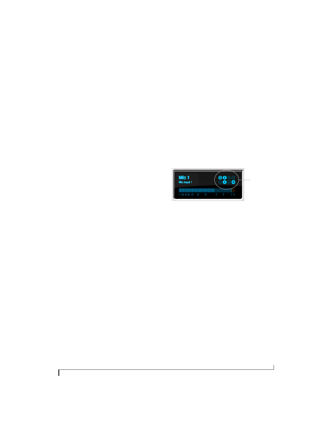
Input meter and bus activity LEDs
When the Channel tab is active (Figure 9-8), the
display above the tab provides a horizontal level
meter and eight
bus activity LEDs
Figure 9-9: Input meter and bus activity LEDs.
The
input level meter
(Figure 9-9) is the same as the
input meters in the Meters tab (Figure 9-22 on
page 89) with the
Pre FX
button engaged, which
shows the input level on the physical input itself,
before any processing of any kind occurs within the
828x. This meter gives you the most accurate
reading of the actual signal level hitting the input,
regardless of any other settings (such as V-Limit,
Soft Clip and so on). The clip indicator, however,
happens after V-Limit and/or Soft Clip. This allows
you to see when clipping occurs, even with these
overload protection features engaged.
The
Bus Activity LEDs
(Figure 9-9) show you
which mix busses the input signal is being fed to.
For example, LED #6 will glow under the following
conditions: the input is unmuted in mix bus 6, its
fader is up, and there is signal activity from the
input going into the mix bus.
Bus
activity
LEDs